Fender Design Challenge
Design of fender –
Objective – To develop the front fender using NX cad following the design parameters given in the master section.
Introduction –
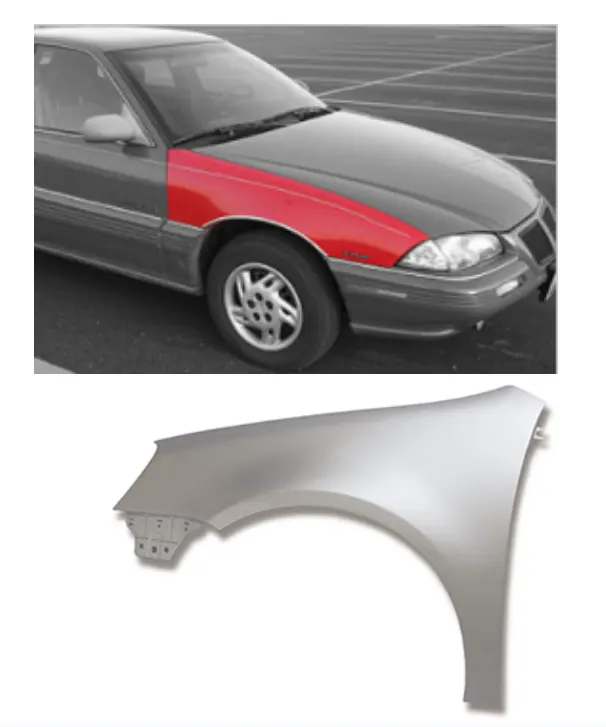
Front fender is a part of the vehicle that frames the wheel. The primary purpose of the fender is to prevent sand, mud, rock etc. from being thrown away into the air by rotating the tire. Fender can be of two type’s full bumper type and half bumper type. Now a days half bumper type fender is typically used the most of the sheet metal blank is reduce as we can produce two half bumper type fender in single blank. This also leads to reduction of scrap produce two half bumper type fender in single blank. This also leads to reduction of scrap.
Design Parameters –
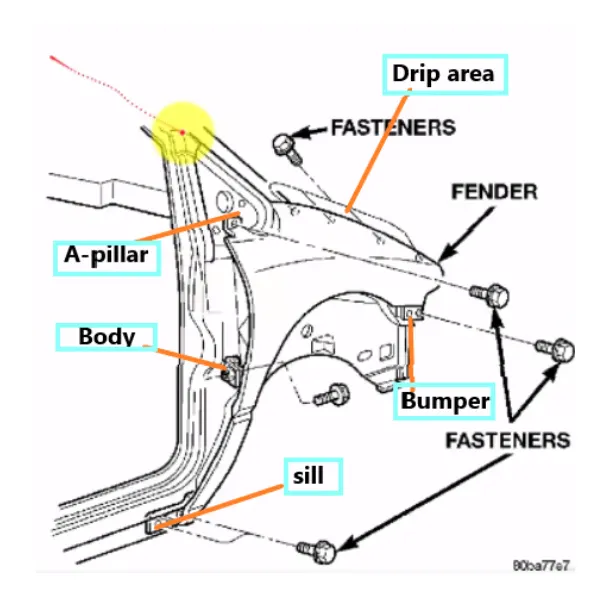
The front fender is manufactured as a separate part this is then mounted to the body of car for this the front fender basically has 5 mounting points but this mounting points can differ from OEM to another OEM below is the points.
- Drip Area –
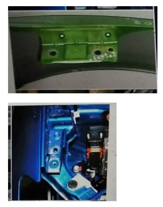
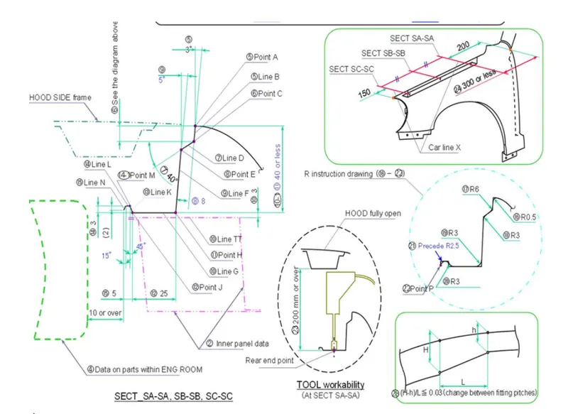
Drip area mounting is the important part in the fender this mounting is attached to the engine compartment of the car. Fender drip area is mounted via weld nuts to the engine compartment a min of 150 mm distance is kept from the front side and a distance 300mm or less can be kept om the rear side. The total length of drip area from the top of fender should be less than 40mm, this is to avoid the spring back during the manufacturing the edge of the mounting should at least 10mm away from any nearby component in the engine. A rigidity bead is provided at the end to increase the strength of the mounting.
- A Pillar area –
The A pillar area mounting depends upon the A pillar of the car. The mounting can also be provided with ribs to strengthen the part. This mounting is critical in design as it has to be mounted on A Pillar properly.
- Body side area –
Another mounting point is created for the body side on the fender. This mounting is created such that it can be mounted on the body of the car. It may consist of one or two bolting holes.
- Sill area –
Sill area mounting Is also an important mounting part this mounting point is basically on the bottom of the fender the mounting part should be created such that the fender is firmly attached to the sill.
- Cowl area –
Sometimes fender is also provided with cowl area mounting this mounting is on the top side of the fender.
Design Procedure –
Input – We have the outer skin of fender as our input.
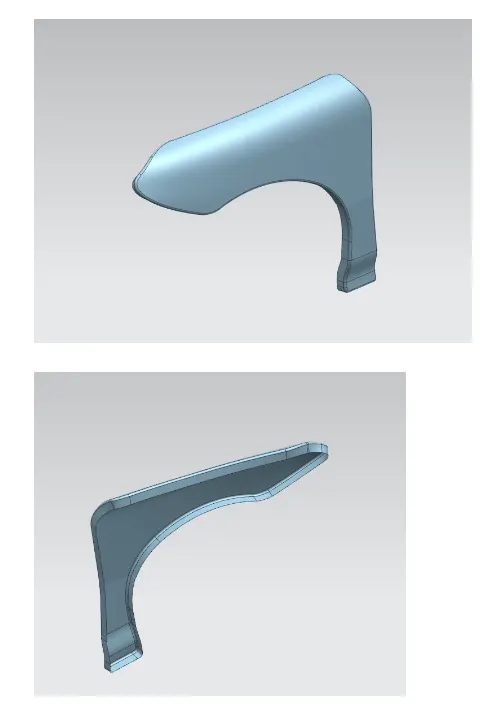
- Drip area –
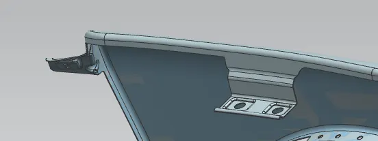
The height of drip area mounting should be less than 40mm so that it reduces the spring back effect during manufacturing.
The edge of the mounting part should be at least 10mm away from the nearby components in the engine.
It should be distanced at least 150mm from the front side and 200mm from the rear side
- A Pillar –
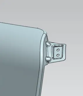
Ribs are provided in order to increase the strength of A Pillar mounting point.
Other factors for the mounting flange will be depend on A Pillar design of the car.
- Bumper side –
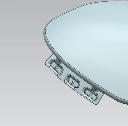
- Sill area mounting -
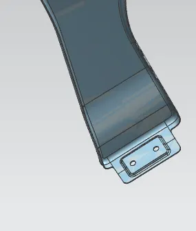
- Baffle mounting –
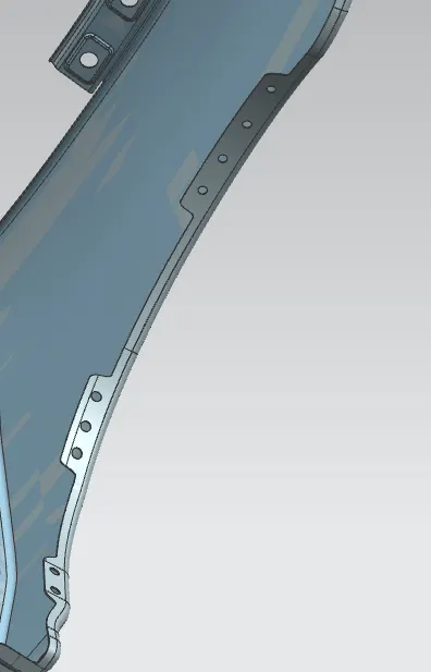
For improvement of NVH in car usually a baffle is mounted on the fender of the car. It is mounted on the wheel arch area.
Distance should be maintain between two holes following the design rule of 2*(radius of hole) or more than 2r.
Output -
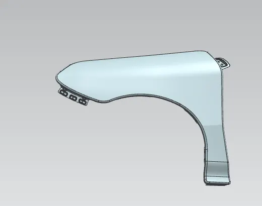
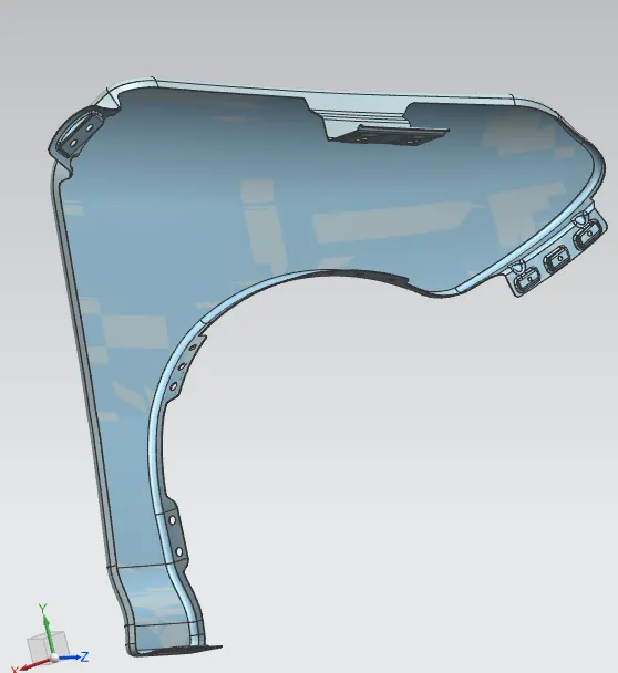
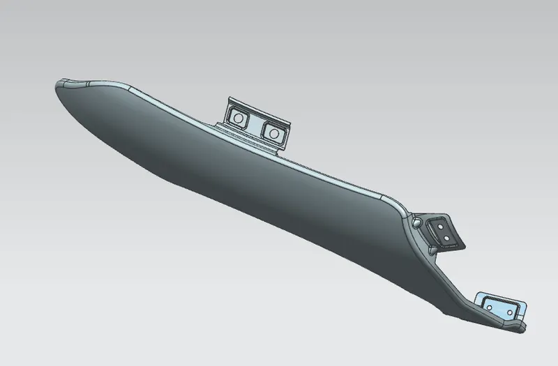
Conclusion –
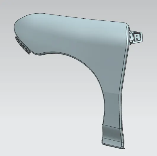
We have developed front fender with mounting points following design parameters and mastersection.