Fender Design Challenge
Design of fender:
A fender is a part of an automobile where the wheel is located under it. Fender is a BIW component which has different constraints for passenger and pedestrian safety.
The primary purpose of the fender is to prevent sand, mud, rocks, liquids etc that being thrown out from the tire onto the road.
These particles tend to come out of the tire and may fall on the pedestrians nearby. So the fender prevents injuries to pedestrians and contains the motion of these particles.
Most automobiles have four fenders on all four wheels. For wide-body vehicles that cover the tire, the fender forms the "wheel well" surrounding the tire.
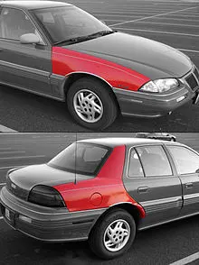
Evolution of Fender:
The fenders have developed over the ages. In the olden days, the fenders were not integrated along with the hood, Instead placed on either side of the hood over the wheels. All the new-age cars have the fenders integrated on either side of the hood. Different types of fender are shown in the below image.

Mounting of fender:
The fender has five mounting points, they are:
1. Body(Chassis of the vehicle)
2. A-pillar(Where the windshield and ORVM are mounted)
3. Sill(Bottom area of the doors)
4. Drip(Area where the fender is mounted in the engine bay without touching the engine and the other components such as battery etc)
5. Cowl(Where the wipers and the wiper assembly are mounted)
Types of fenders:
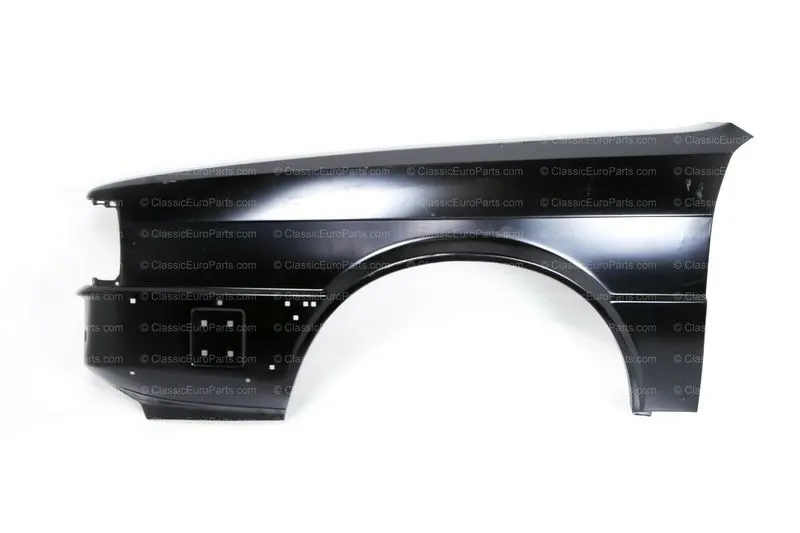
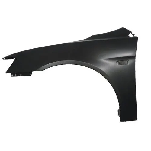
There are two types of fenders one is a full bumper type and the other is a half bumper type.
full bumper type fender
half bumper type fender
Manufacturing a full bumper type fender results in difficulty of production and lots of material goes under wastage after the production.
But the half bumper type fender is easy to manufacture because the design is more simple than the full bumper type and the material wastage is very low.
All the automobiles in the present generation use half bumper type fenders to reduce the cost and material wastage.
Design considerations for fender:
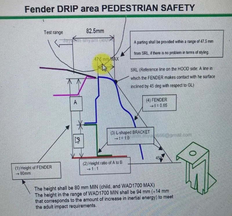
As shown in the figure, when a line is drawn from the ground at an angle of 45 degrees, the line should touch the curvature of the fender when the width of the fender from the hood edge is 47.5mm. This is the maximum width that a fender can have. If the line drawn from the ground doesn't touch the fender then the curvature of the fender should be modified. The L-shaped Bracket is added to join the bottom part of the engine bay to the bottom face of the drip area.
Given Master section to design the fender:
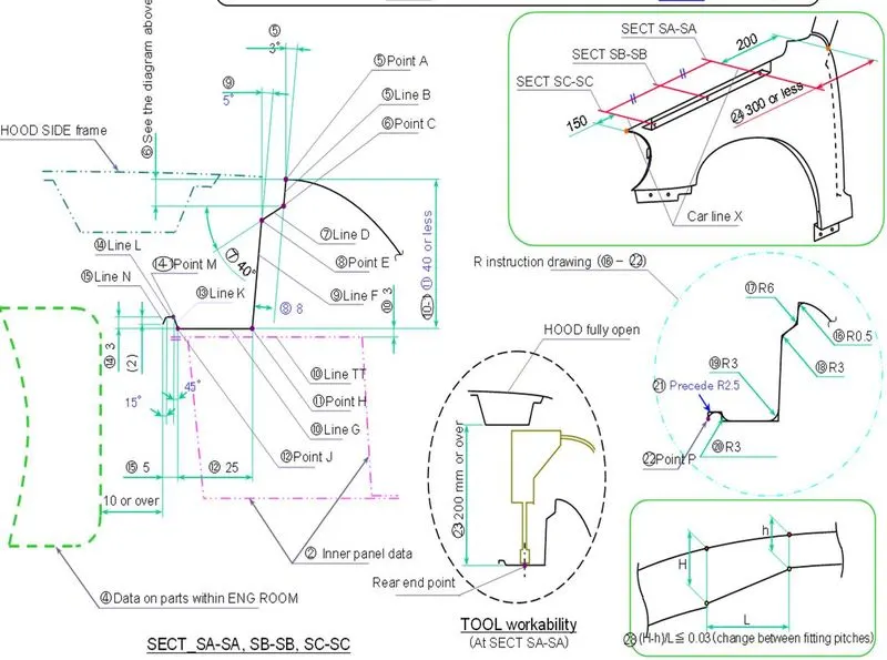
As shown in the image the most important region for the fender is the Drip area. From the A-pillar mounting the drip area must have a clearance of at least 200mm and from the headlight area it should have a minimum of 150mm clearance. The area which is left after leaving this clearance can be used as the Drip area. This drip area is mainly used to mount the fender in the engine compartment under the hood.
When the hood is fully open, there should be a minimum gap of 200mm and can be more from the fender drip area to accommodate space for the tool to work inside the engine compartment.
From the outer edge of the fender to the inner edge of the fender in the engine compartment, there should be a minimum gap of 82.5mm, so that the fender doesn't interfere with the parts in the engine compartment.
From the top edge of the fender to the drip area the length should not exceed more than 40mm. If the length is more it leads to the spring-back effect. This increases the vibrations and noise in the engine bay decreasing the overall NVH levels of the car.
When looked at from the outside of the car, it looks odd when all the mounting and engine parts are visible. To hide all these parts the inner edge of the fender is extended at an angle of 40 degrees. To reduce the edges in the design, fillets are provided with a radius as shown in the figure.
given skin data:
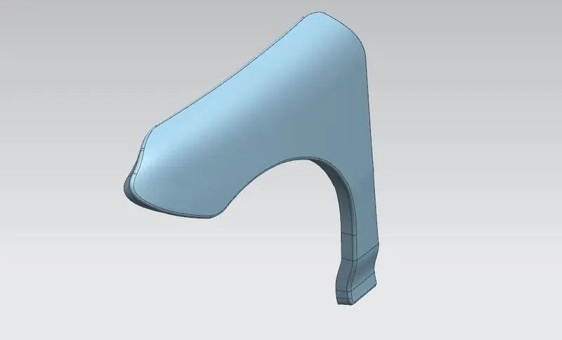
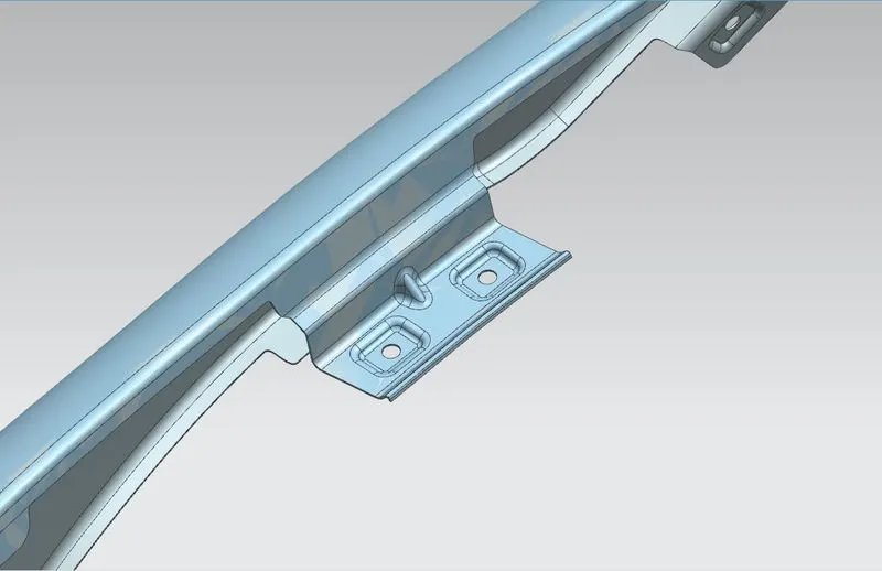
From the fender skin data, we create the drip area and all other mounting areas. To perform these operations, we start from the styling point. From the styling point, we take a 3 deg angle because it is the minimum required angle for the tool to produce a part. With the 3 deg angle, we go 9mm deep which is the minimum requirement of the design. From there we open an angle of 40deg with a width of 8mm. As said before this 40deg angle cuts off the visibility of the parts under the hood to the observer watching from outside of the fender. After this, we extend the sheet to a length of 35mm to 40mm with an angle of 5deg. This extended sheet is used to create the drip area by creating a law Extention in the horizontal direction. On this horizontal plane, we create an emboss for the mounting of the fender and also include darts to give additional support to the sheet metal. In the same way, we create embossed at the A-pillar mounting, sill area and bumper mounting regions. The baffle region is the area where a foam-like product is installed which absorbs the vibrations from the fender and reduces the noise that comes from the road through the fender area. The baffle helps to absorb the road noise and vibrations helping us to improve the NVH levels of the car. But installing a foam-like structure in the baffle is completely dependent on the budget of the car. In low-budget cars mostly the baffle is not accommodated with the insulation but in premium cars, it is included. The fender is also divided into many categories where it can have a signal indicator, wheel arches, ORVM mountings etc. Based on the model and based on the price of the car these things are evaluated.
The images of design of the fender are shown below:
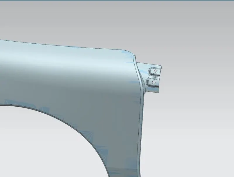
A-pillar mounting.
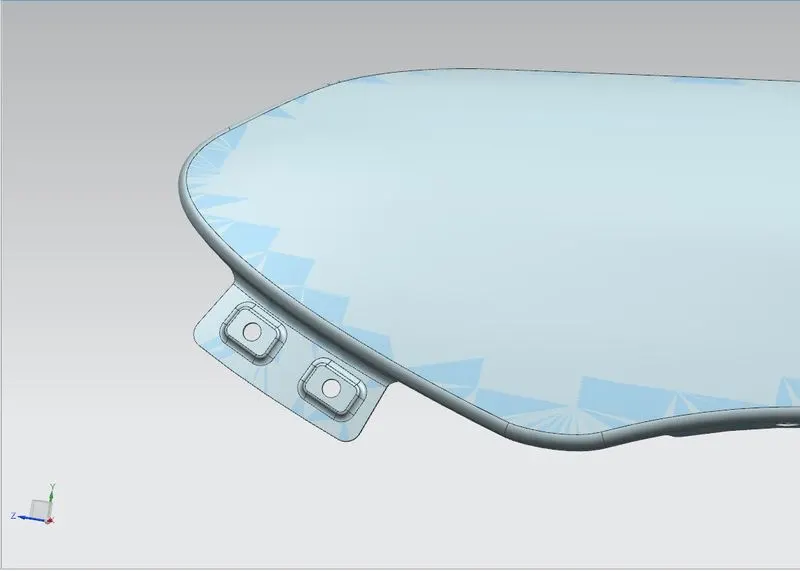
Bumper mounting
sill mounting
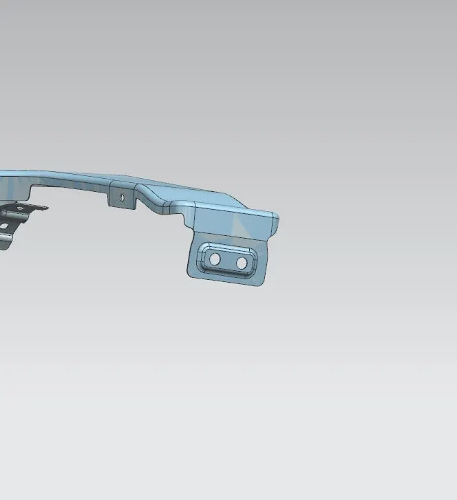
Baffle region
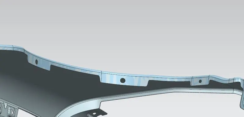
Drip area
Conclusion:
As per the given master section and the parameters that are set to design the fender, The front fender is designed with all the mounting points.