Fender Design Challenge
Fender Design
Aim:-
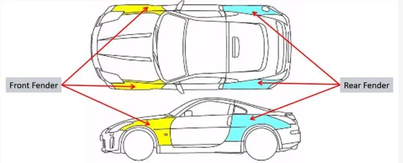
Its primary purpose is to prevent sand, mud, rocks, liquids, and other road spray from being thrown into the air by the rotating tire.
Introduction:-
Sticky materials, such as mud, may adhere to the smooth outer tire surface, while smooth loose objects, such as stones, can become temporarily embedded in the tread grooves as the tire rolls over the ground. These materials can be ejected from the surface of the tire at high velocity as the tire imparts kinetic energy to the attached objects. For a vehicle moving forward, the top of the tire is rotating upward and forward, and can throw objects into the air at other vehicles or pedestrians in front of the vehicle.
Type of Fender
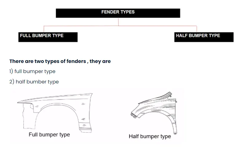
- Presently we are using the half bumper type,the reason for choosing the half bumper type is that when we choose the full bumper type the blank used for creating it is very large and also has the lot of wastage, but in the case of the half bumper type we have the possibility to reduce the scrap.this is what we called as scrap management.
- in half bumper type we reduce the use of the steel material and use the lost of plastic on the bumper which in term decreases the car weight and increases the performance.
Design Methodology :-
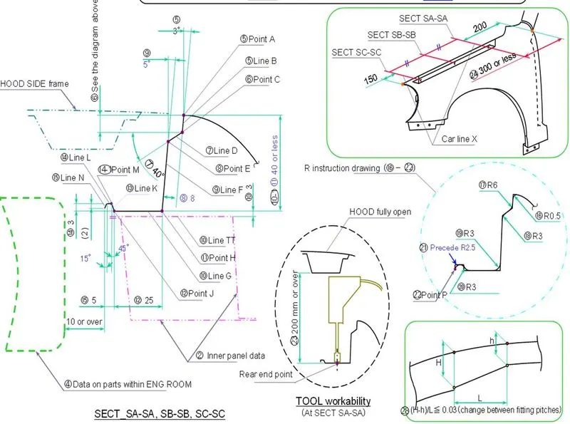
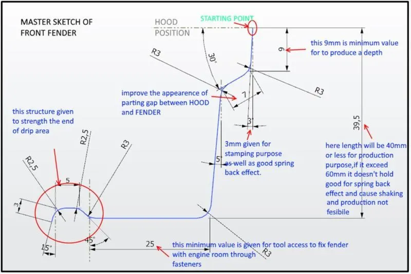
Given data Master Section
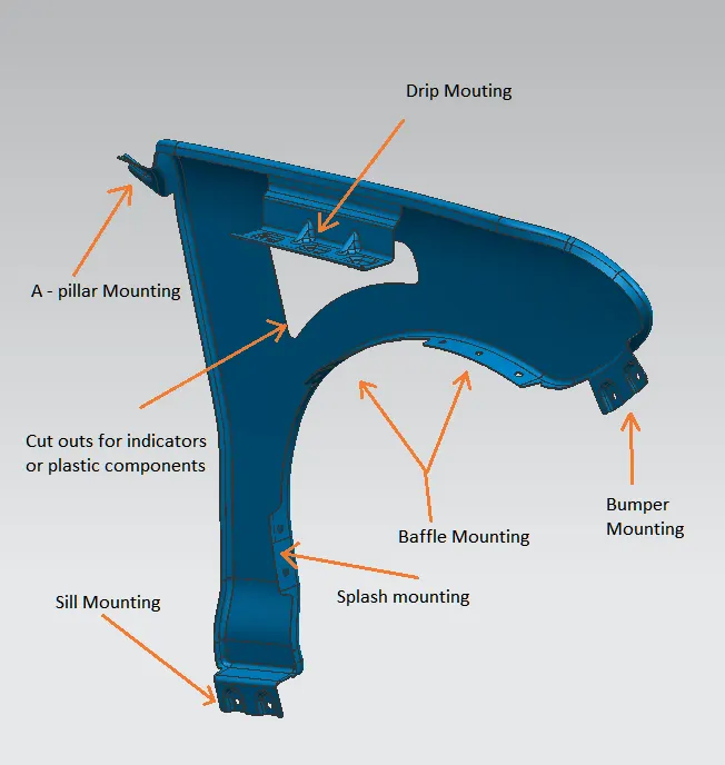
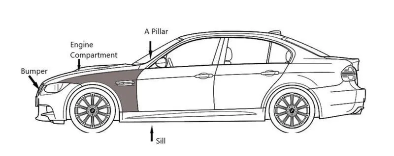
Mounting Regions On Fender :
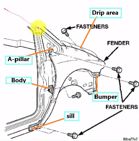
Ther are 5 mounting regions on the fender.
- A-Pillar mounting
- Body mounting
- Sill mounting
- Bumper mounting
- Drip mounting
Design of drip area mounting :
- It is important mounting unit of the fender it is connected with the engine compartment , there for lot of design constraints are to be followed while designing the fender
- while designing the drip area we have to initially leave 200-300 mm for cowl top
- for placing the headlamp we have to leave at least 150mm at the front while designing the fender
- Cowl top part consists pf wiper motor and it instruments
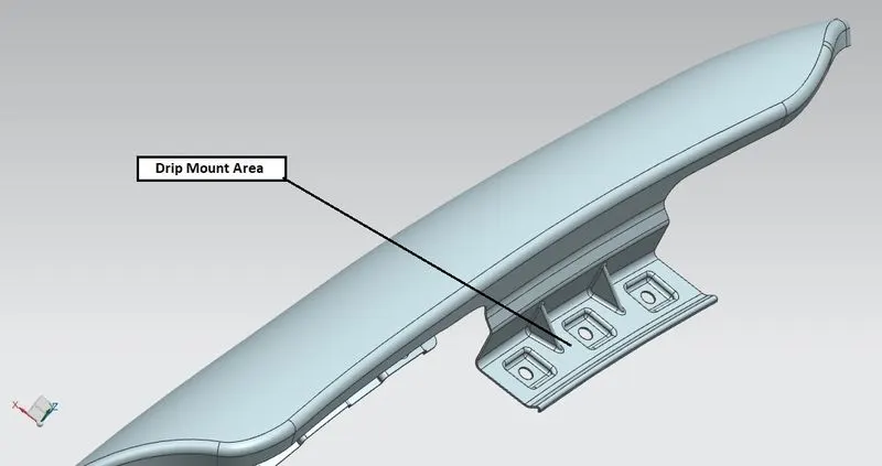
- two part are added on the longer side of the drip area in order to provide the stiffness adds strength to the part.this help the fender to not to vibrate and impact the forces outside of the fender during motion of the vehicle.
- Embossing are provided on the mounting
- Height of fender can be minimum 80mm for child and adult (94mm,WAD 1700MAX, this +14 for increase in inertial force due to accident) impact.
- Parting will minimum 5 not more than 50mm from SRL ( a reference line on HOOD side, a point on fender makes from a line of 45 degree from ground level ).
- Drip area will not reach the engine assembly due to restriction of 40mm length, so there will some L-Shaped Bracket to connect with it.
Picture of drip area mounting.
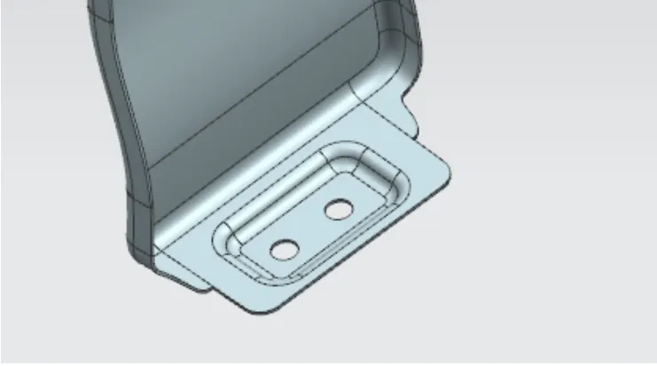
Design of Sill mounting Area :
- Sill is the panel directly below the bottom of the door supporting the floor and may be used to combine the floor and the body.
- the bottom and of the fender is mounted on the sill body for reinforcement of the fender panel, thus the sill mounting position is designed with holes and emboss. M5 fasteners are used to fix the fenders on the sill body.
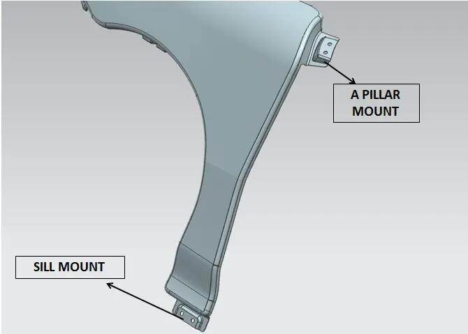
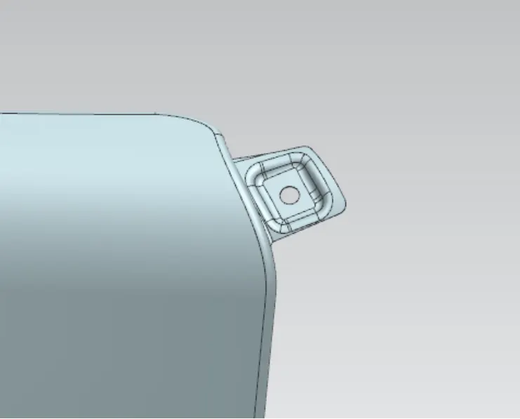
Design of A-Pillar Mounting Area :
- The A-Piller is the structural piller that combines the body to the roof.
- this make the sides of the windshield rest.
- Front fenders are fastened to the A-Pillar to from a robust structure.
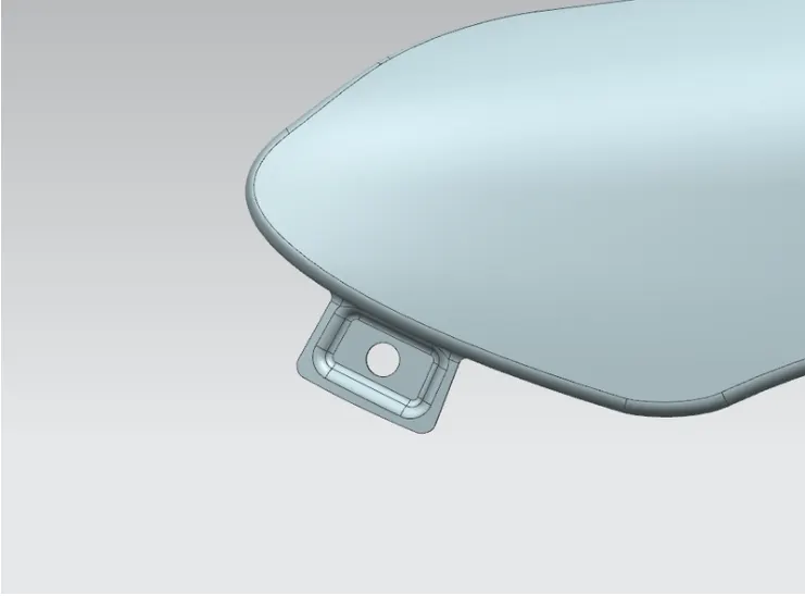
Design of Bumper Mounting Area :
- Bumper mounting area is used to fix the plastic bumper to the fender with the help of the fasteners.
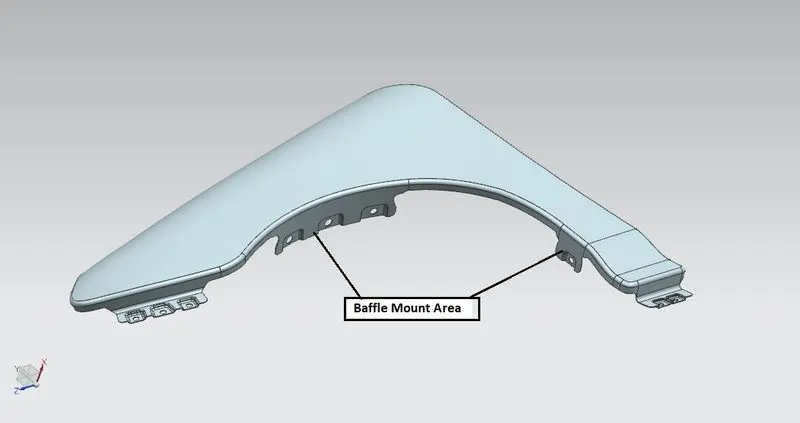
Design of Baffle Mounting area
- Baffle mounting or mudguard are clip fit type of mounting on the inner side of the fender arch over the tyre.
- it protects the car engine compatrment and pedestrians from causing injuries from chip out debris on the road when the car is in motion.
- they are mounted on the fender using a special type of locking clips which are made up of plastics
- The thickness of 0.75mm inward on the final sewed surface of the fender to the sheet metal parameters
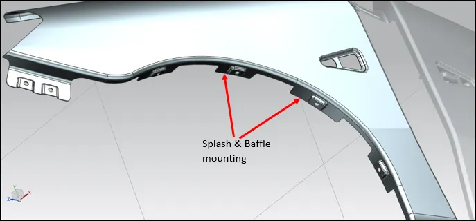
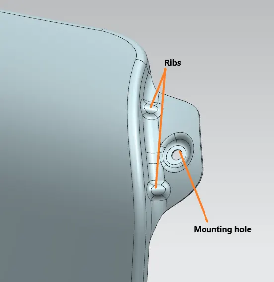
Design of Ribs and Mounting hole
- A vehicle instrument panel support structure is provided having fixing and mounting surfaces linked together by ribs in an open space frame structure.
- The ribs are sized, shaped and positioned to create critical load paths and eliminate the outer skin of the instrument panel support structure. Magnesium alloy material is only placed where it is needed for structure and function.
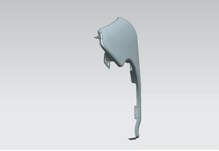
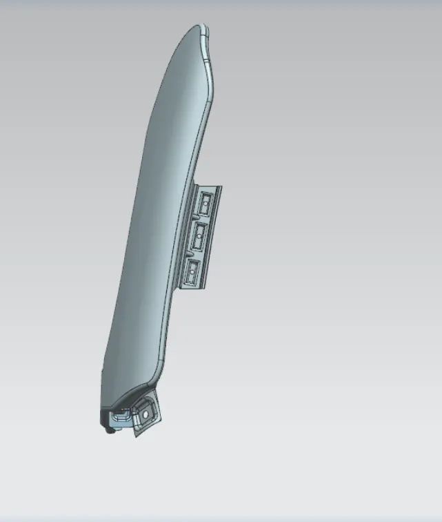
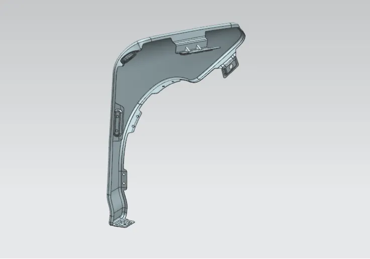
All the part mentione in the below picture :
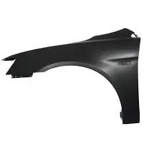
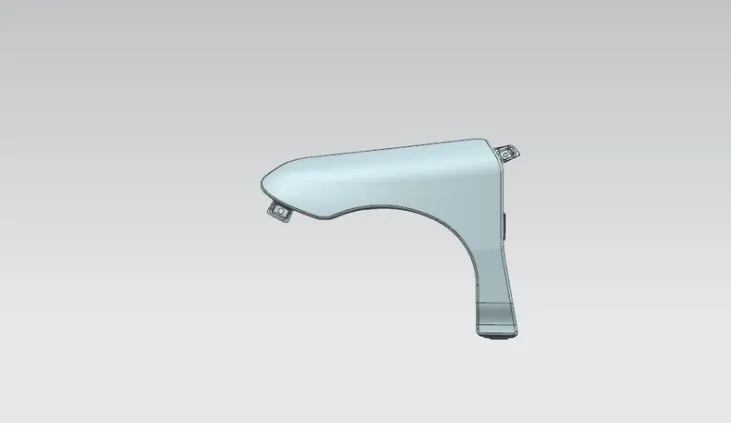
Different Views of Fender :
Conclusion :-
Thus the Car bumper front fender and mounting portion for the attachment component has been designed and studied the function of all the all the mounting area thus gained the knowledge of design and manufacture aspect of the cars.