Fender Design Challenge
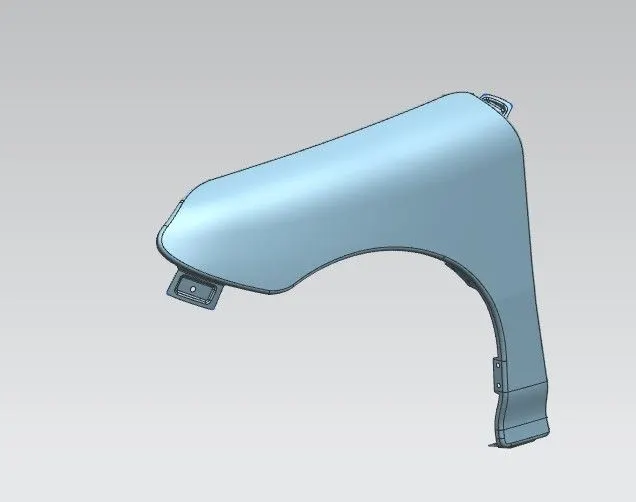
Fender Design
Abstract
To create the fender with help of Siemens NX 12.
santhosh sivan
Introduction
The fender is curved shape structure which is located by side of all vehicles and it coves the wheel and protect the passenger for small rocks, sand and some other particle which thrown by tires while running the car and also it gives good look to the care.
And also, the fender not only protect the car and also the passenger for debris while moving the vehicle also, it protect the car from the debris thrown by other vehicles like truck, four-wheeler, two-wheeler. That’s why vehicles with large, Oversized tires are often required by law to install the fender.
For fender they are two types. One is half fender and another one is full fender. But most of the case half type fender is use. Because it’s easy to make, less economical and easy to install.
To design the fender, they are some commands are use as following below.
- Curve on surface
- Trim sheet
- Law Extension
- Datum Plane
- Intersection Curve
- Trim sheet
- Dart
- Face Blend
- Bridge curve
- Emboss
- Edge blend
- Extend sheet
- Sew
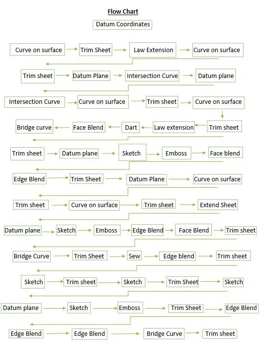
This are commands we used to design the fender as per the industrial aspect. Now we can see how to create the fender and also how the following commands are work with the help of flow chart.
Types of mounting Points in a fender:
In fender they are five types of mounting points.
- Drip Mounting
- A-pillar Mounting
- Sill Mounting
- Cowl Mounting
- Bumper mounting
Drip Mounting:
What is meant by drip mounting.?. which means to connect the fender to engine compartment with help of supporting items like bracket, screws, etc.
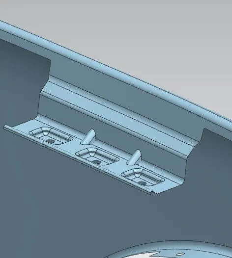
A-Pillar Mounting:
A-pillar Mounting means the pillar region of the fender which lies on the chassis frame. So that it is rigidly attached on the body of the car and it connects the fender to the frame of the windshield
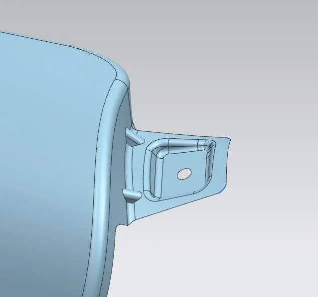
Sill Mounting:
Sill mounting is nothing but the bottom face of the fender (sill region) is attached to the vehicle frame with help of screws or some strip (clip) buttons.
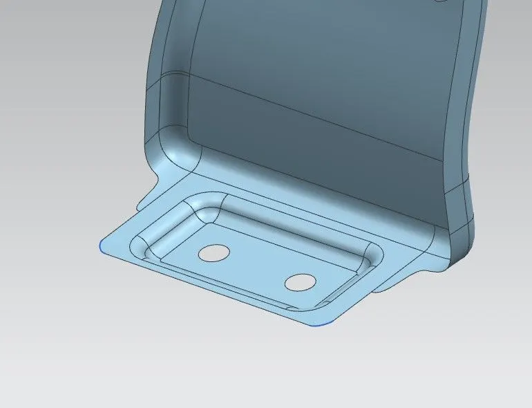
Cowl Mounting:
Cowl mounting, the plastic material which attached with baffle by using clips which hold the baffle along the fender with wheel arc
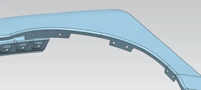
Bumper Mounting:
Which means the region to mount the fender to the vehicle bumper.
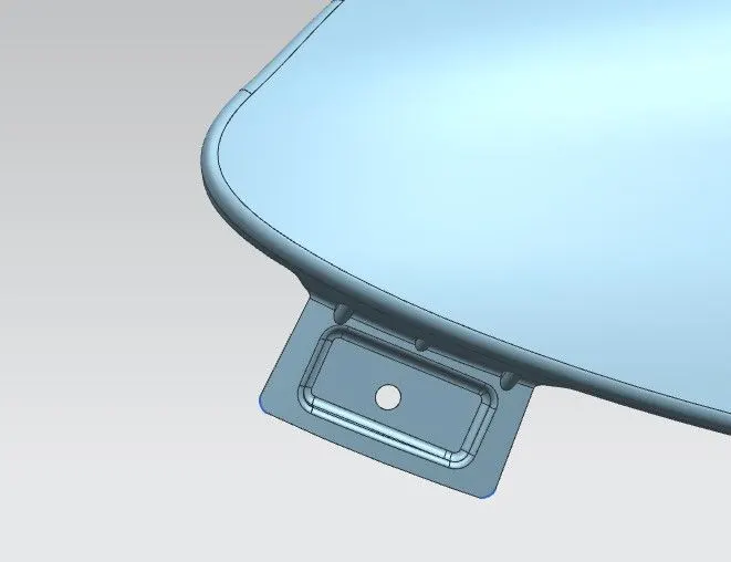
Master section for Drip area:
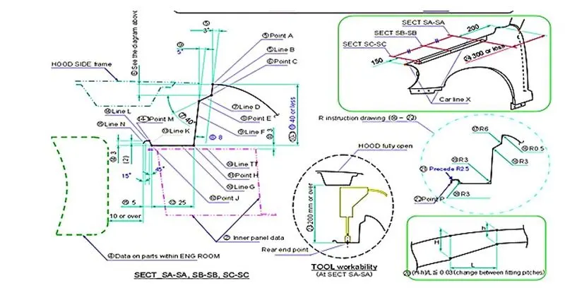
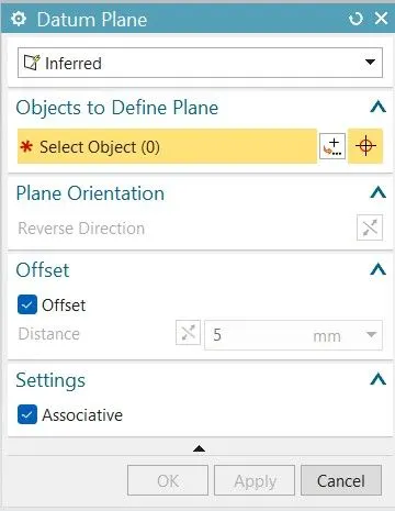
Datum Plane:
Datum Plane which means a grid is a localized grid that helps you work on an object in your model. Grids typically provide the context of location and size to objects. You can create or edit a datum plane grid in any application where you can create a datum plane, such as Modeling. The following figure shows a datum plane grid.
Trim Sheet:
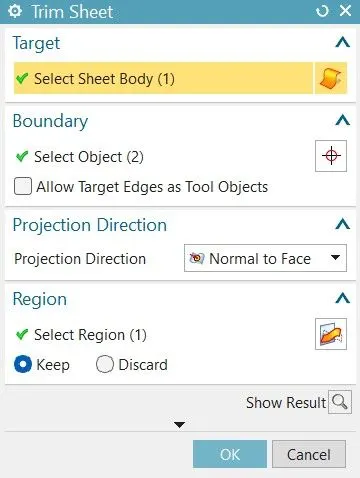
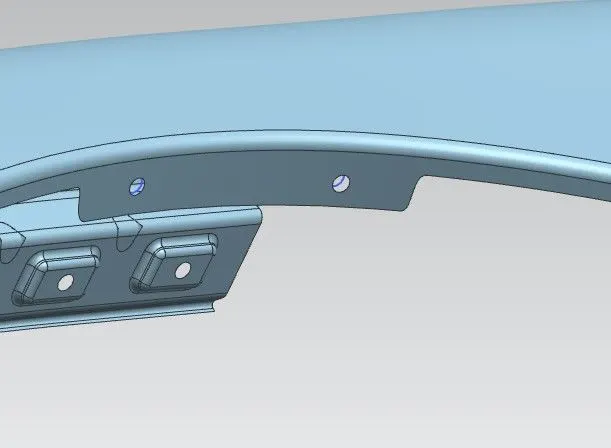
Trim sheet means to remove unwanted portion from the component. First you can create the part and select the unwanted portion and click trim option. In that option select the sketch and click ok. For example, you creating the hole on particular area, first create and then click trim option then select the sketch and click ok.
Law Extension:
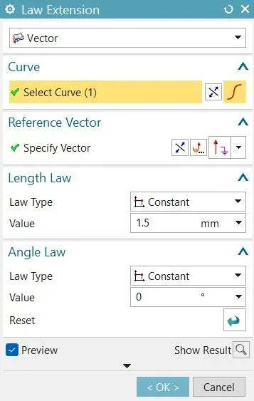
The law extension means to extend the sheet by use both vector and face and also create the surface in different angle by selecting or using law extension commend.

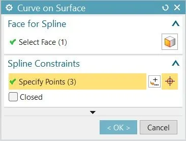
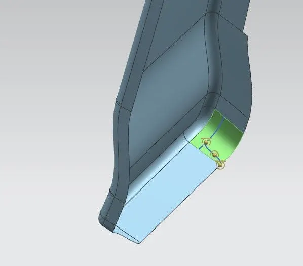
Curve on surface:
Which means allow to draw the curve on selected body or face. In this command they are three continuities first one tangent continuity G1 second one is curvature continuity G2 and third one is point continuity. With help of this option, we use to create a curve on the surface.
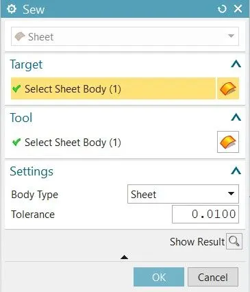
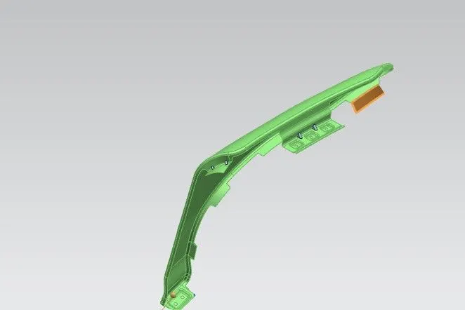
Sew:
Sew which means to combine two parts into single part
Intersection curve:
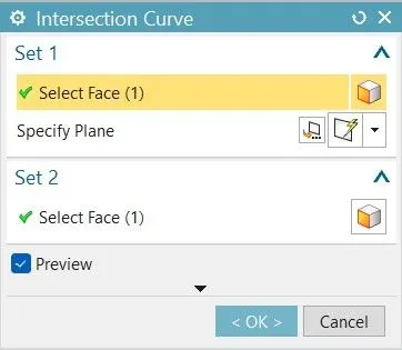
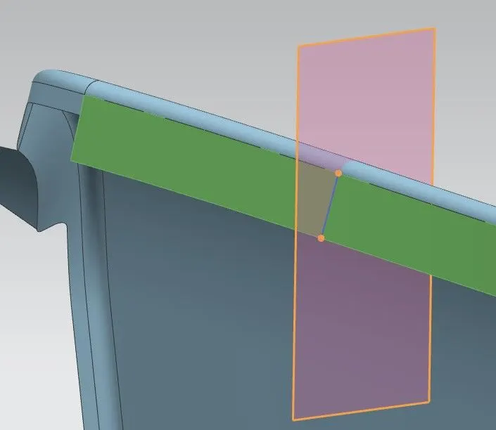
Intersection curve means to creating curve from two intersections by select the face or select the edge on the plane (datum plane) and click ok.
Dart:
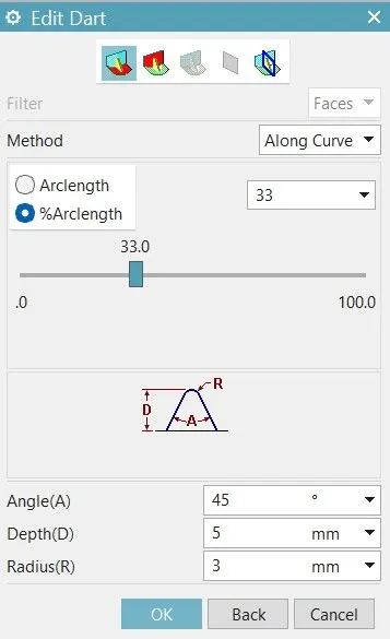
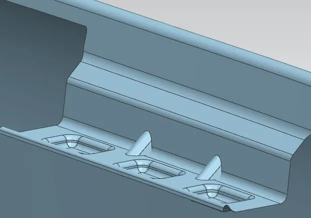
To add this feature along the intersection curve of two sets of faces and also it provides extra strength to the component. Select dart or click insertàDesign featureàDart then selects both face and click ok.
Bridge curve:
Which means to create the tangent blend between two objects. In this option we can change the arc length with the help of connectivity option in bridge curve property manager.
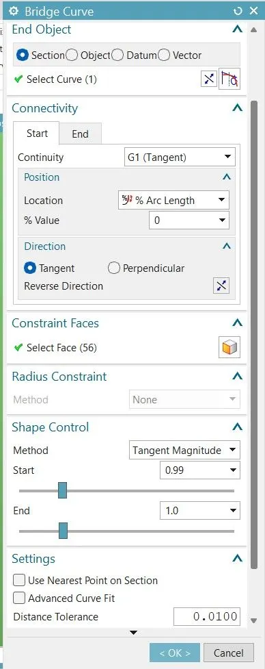
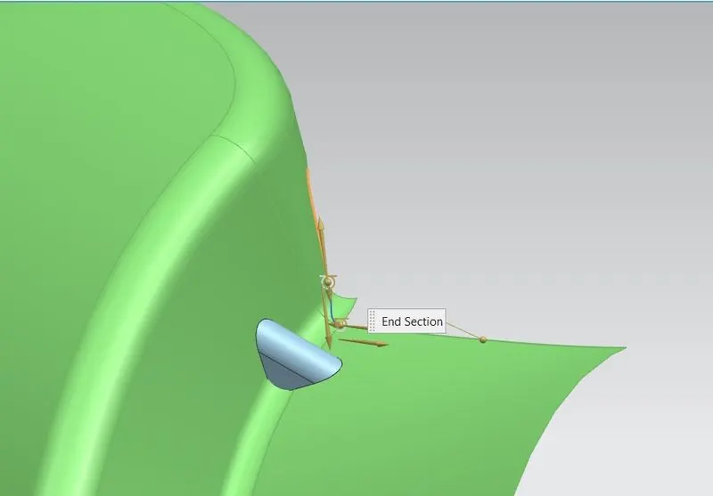
This are some tools we can use to create the fender
Fender design:
First create the curve for pillar mounting by using curve on surface command. Then select trim sheet to remove unwanted portion from the component. Then, extend the sheet of particular direction with the help of law extension. After that create datum plane for drip mount.
Click Intersection curve and create the line for trim for both side. Now select trim sheet for removing the required portion. Again, click curve on surface command for bumper mounting. In surface command give tangent G1 for starting point on the curve and end point on the curve, in all curve on surface for give smoothness and good look for fender.
Same click law extension command for drip mounting by different angle. Then create the dart for provide extra strength to the drip. Because, in that particular part has more vibration and load when compare to other mounting areas. After creating dart now apply face bend for every corner for smooth curvature.
After that create emboss on datum plane. Now sketch circle for mounting holes and trim it. Same procedure done for create remaining mounting areas.
Fender Design:
Fender front view:
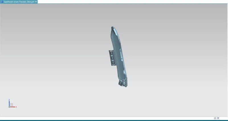
Fender Right side view:
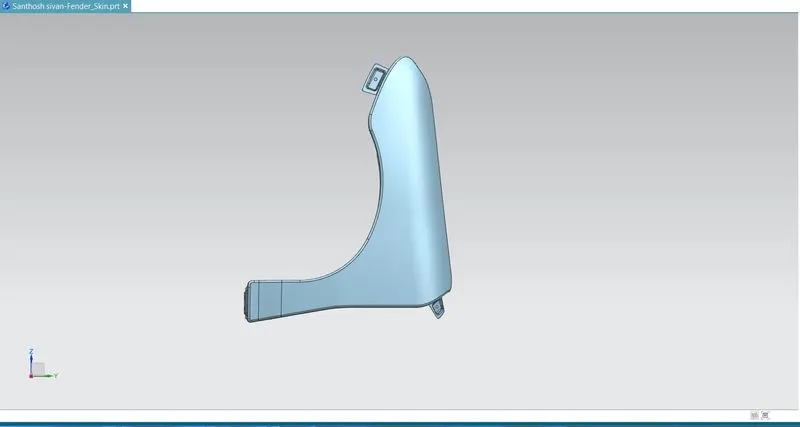
Fender Top view:
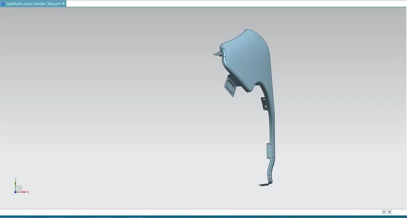
Fender Isometric View:
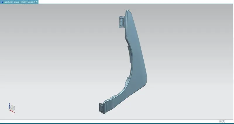
Fender History tree:
History tree 1:
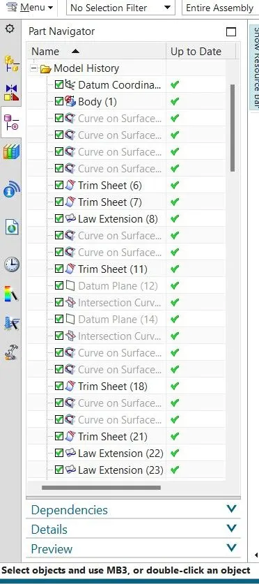
History tree 2:
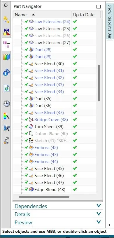
History tree 3:
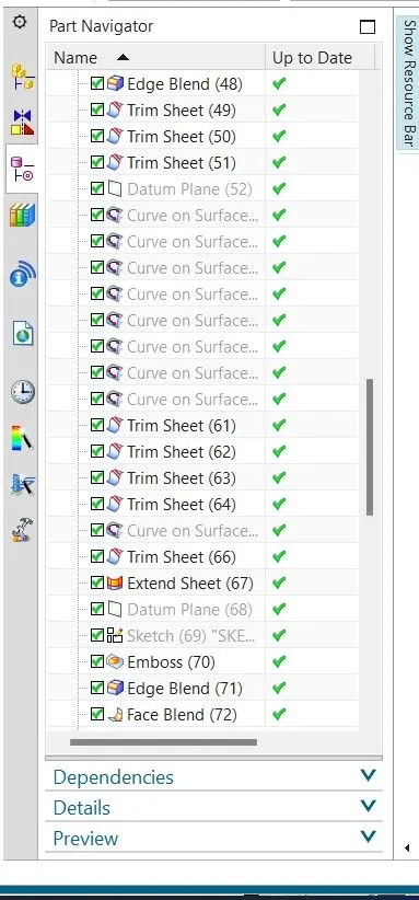
History tree 4:
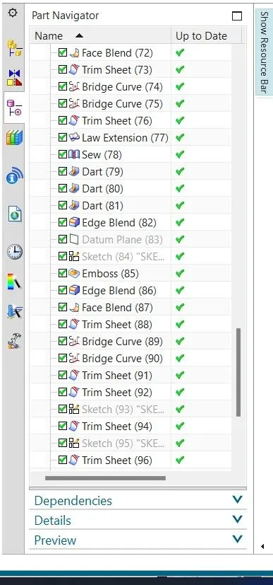
History tree 5:
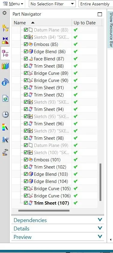
Conclusion:
In this fender design I conclude that the fender was designed as per the dimension and also, I understand the functions of tools, their functions.