Fender Design Challenge
FENDER DESIGN CHALLENGE
So now we all know that what fender actually is, as we have learned in the earlier challenge of wheel arc calculation. Here we are given the new challenge to design the fender according to the masters section provided.
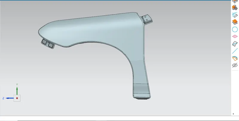
So the Class A Sheet Metal Surface of the fender is provided to us as an input as shown in the figure below.
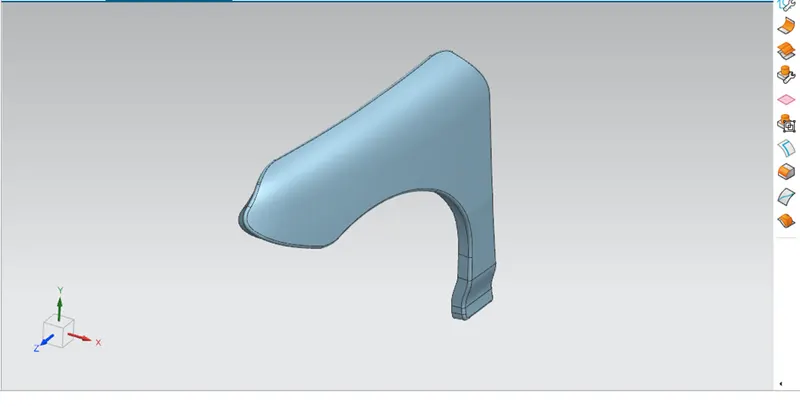
The above given is the Class A Sheet Metal Surface of the fender.
Here we need to design the fender according to the masters section provided to us as shown in the figure below.
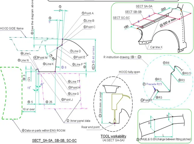
Now as we have the master section initially we need to study it and then we can proceed for the design. By visualizing the master section we got to know that the fender have itself total 5 mounting places they are named as follows:-
- Drip area:- The drip area is the area between the closed hood condition and the fender. Basically it is the mounting created on to the fender for joining purpose.
- Bumper area:- The bumper area on to the fender is created in order to join the fender with the bumper.
- Sill area :- This is the bottom area of the fender where the mounting is created in order to join the fender with the body.
- A pillar area:- The A pillar area is the upper area of the fender where the mounting is created in order to join the fender with the A pillar.
- Baffle area:- Baffle area is the inner curve area of the fender which is used to mount splash or baffle in order to protect the automotive from the unwanted stones and water entering the engine compartment.
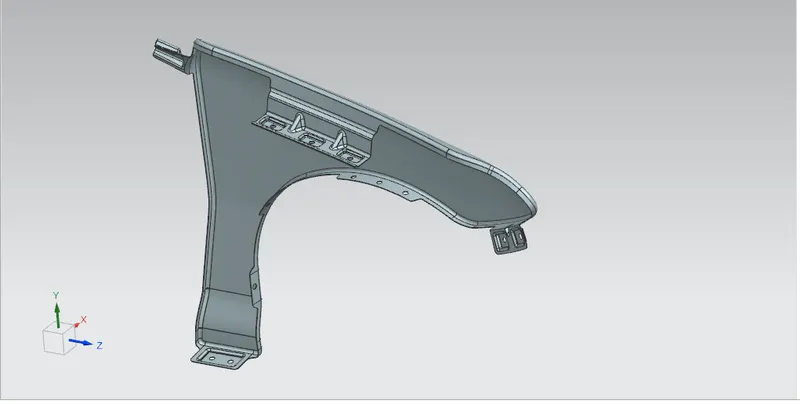
All the important mountings are shown in the given figure below.

Now as we all got to know the mountings points and where are they actually located we need to study the master section for the drip area.
So the master section of the drip area is given as follows:-
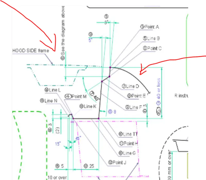
But before creating the drip area we need to understand the design rule that where actually can we create the drip area.
So according to the design rules and considerations we need to give the tolerance space of 200mm from the backside of the fender and 150mm from the front side of the fender.
Here we have created the plane at the given distance from both the ends and then we have created the intersection curve and then the drip area is created as shown in the figure below.
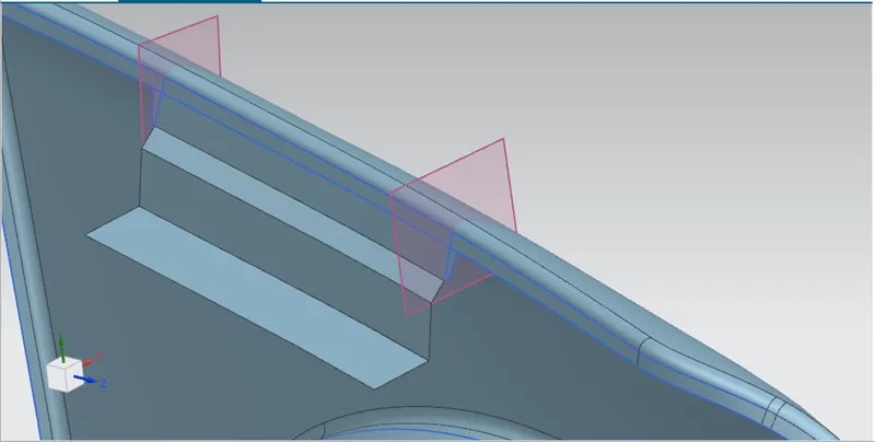
But here at the end of the drip area have some designed structure to provide the strength to the flanges. Here is the detailed view of the structure.
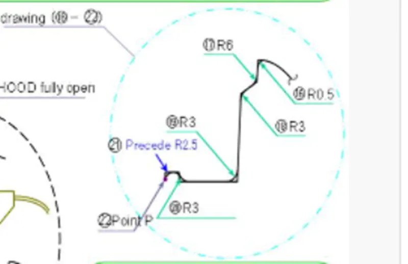
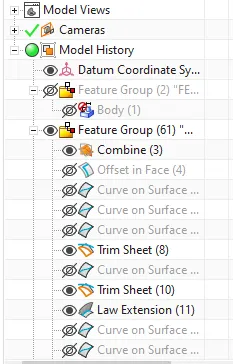
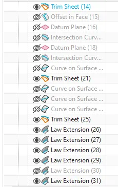
The same design structure is created using the law extension command as shown in the figure. Here the value of the structure is find out using the Pythagoras theorem and the trigonometry relations.
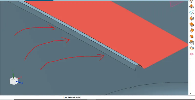
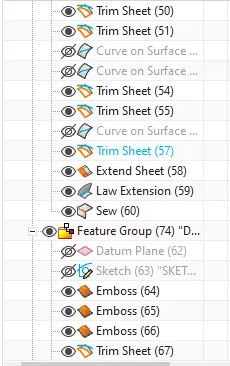
Now as the drip area is created the mounting points should be created with the circle diameter of 6mm and giving the emboss of 3mm at 10 degrees along with the dart to provide the strength to flanges as shown in the figure below.
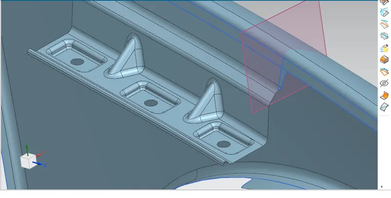
Here the diameter of the circle used is 6mm and the dart dimensions are radius 3mm, depth 10mm and angle 45 degree. So the dimensions provided here is not necessarily used, it totally depends upon the designer’s choice that what should be the perfect design, sketch as well as dimension.
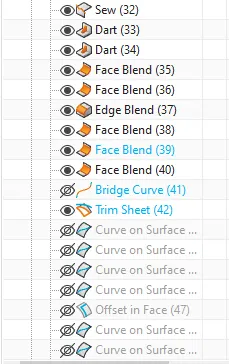
After the whole design the face blends, edge blends are applied to give the smooth texture to the design.
Now as we have designed the drip area according to the master section we need to finalize the positions of the other mountings places.
Now again here there is not any dimensioning criteria for making the mounting surfaces, it depends on the designer how he wants the design to be.
So here one by one the mounting surfaces are created for the Sill area, A pillar, bumper area and the splash/baffle area as shown in the figure below.
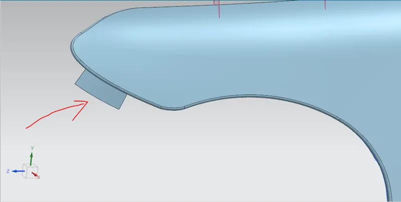
Bumper mounting area.
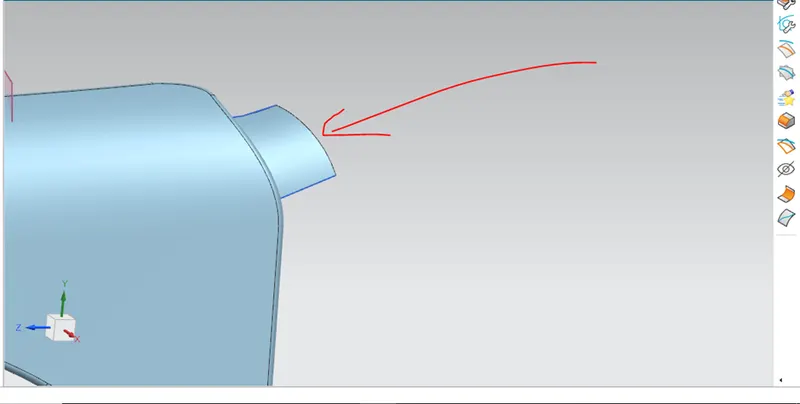
A pillar mounting area.
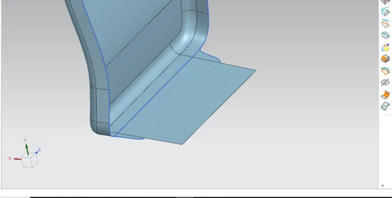
Sill mounting area.
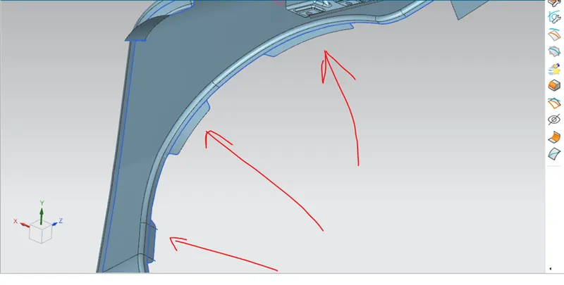
Baffle mounting area.
So now we have created the surfaces for the mounting, our next task is to create the mounting points in order to provide the joining points to the fender.
Here initially the sill area mounting points are created. The sketch is drawn and then the emboss command is used with draft of 10 degree and 3mm in height as shown in the figure below.
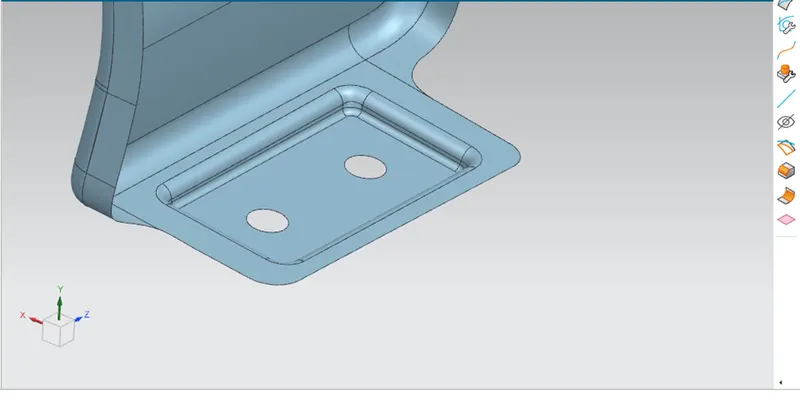
Ok here the sharp edges of the sheet metal are given the relive in order to avoid any kind of the design error.
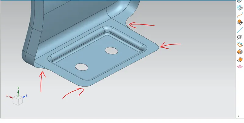
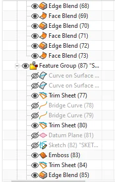
Design relives are given using the bridge curve command.
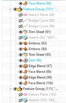
This same process is done for all the mounting surfaces as shown in the figure below.
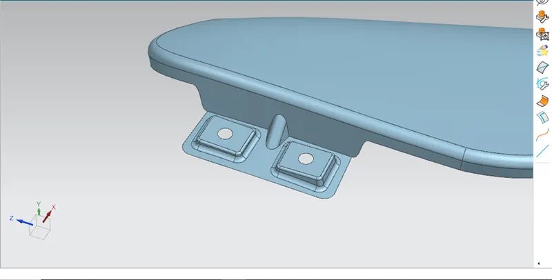
Bumper mounting points with dart.
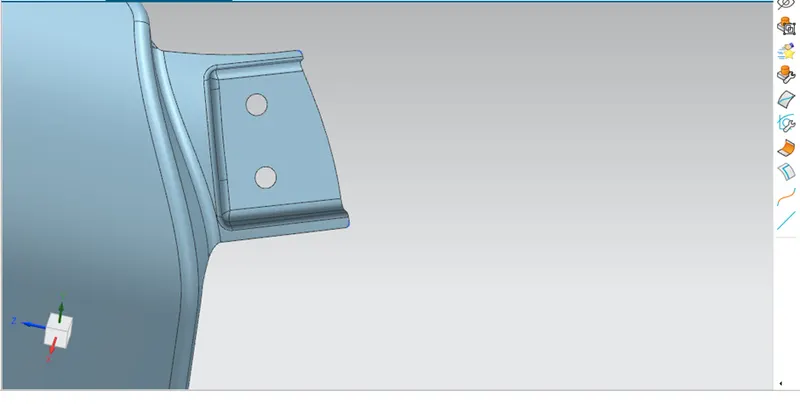
A pillar mounting points.
But only in the baffle mounting area embosses are not been created, here directly the points are designed as shown in the figure below.
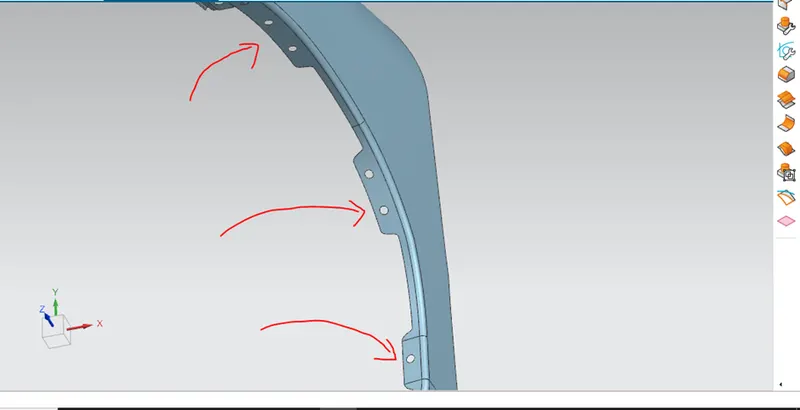
Baffle mounting points.
Here now our full design of the fender is ready as shown below:-
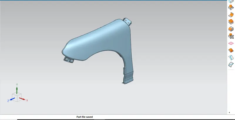
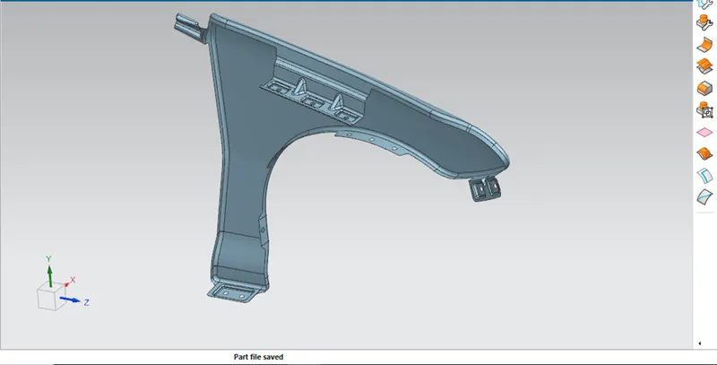
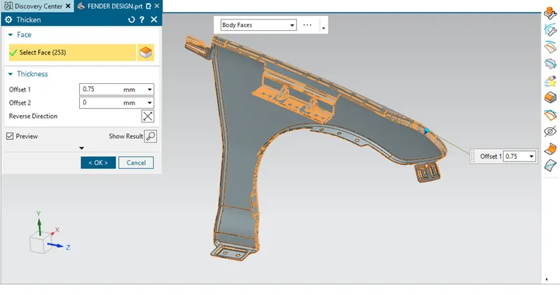
Now the final step is to provide the sheet metal the thickness i.e to convert the sheet into solid.
Here the thickness of the sheet metal given is 0.75mm as shown in the figure below.
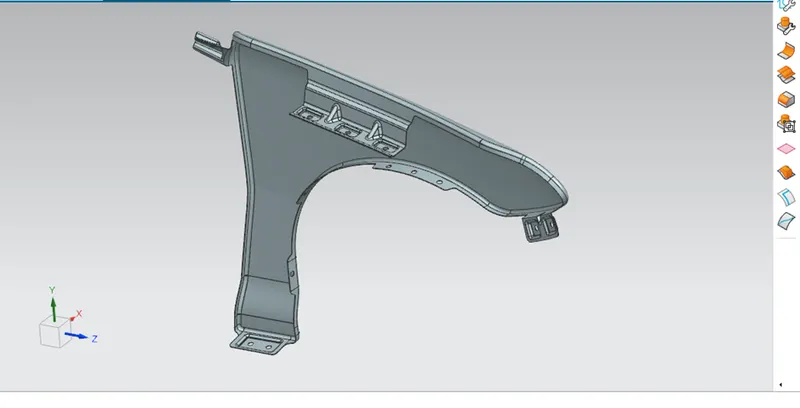
Hence we have successfully completed the fender design challenge.
IMAGES:-