Fender Design Challenge
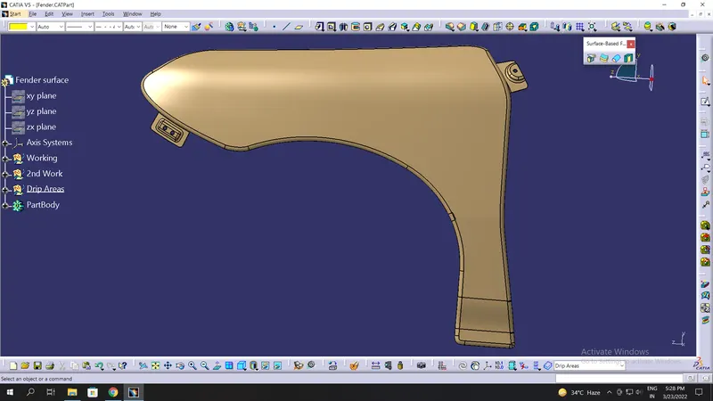
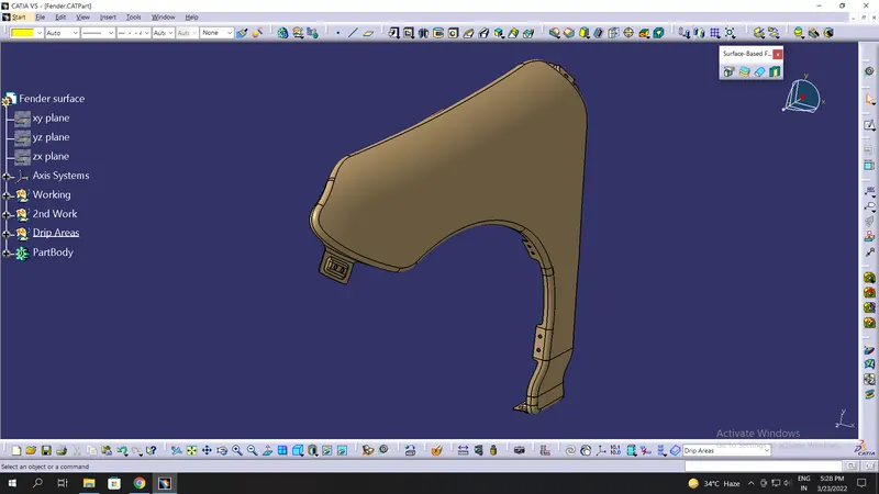
*Designing Front Automotive Fender.
Given Input:
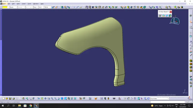
Introduction:-
The design of any product starts from a requirement.The design engineer sketches the product based on the requirement. Then the 2D sketch with the proper dimensions is converted into the 3D model using the advanced CAD software.Another important thing in the design is that every product that si designed should be able to manufacture.So the role of the design engineer is to design a product that can be easily manufactured and with less cost-effective.This is the place where the design for manufacturing(DFM) and Design of assembly(DFA) take a role while developing any product.The process of development of design carries on until the design satisfies the customers's needs.Here in this project the product that we are going to develop is a car fender.
Fender:
The main purpose of the fender is to prevent sand,mud,rocks,liquids and road spray from being thrown into the air by the rotating tire.
Types of Fenders :-
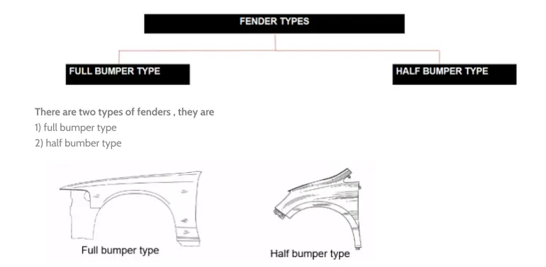
Presently we are using the half bumper type,the reason for choosing the half bumper type is that when we choose the full bumper type the blank used for creating it is very large and also has alot of wastage,but in the case of the half bumper type we have the possibility to reduce the scrap.This is what we called as scrap management.
Fender Wheel Arch:-
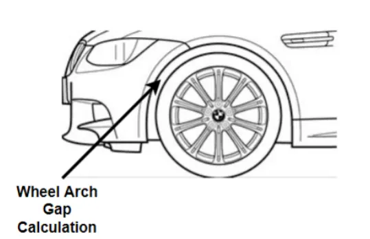
The fender wheel arch is having some standard specifications.For example,if you see the car from the front,if you see the wheel outside the fender it does more chipping and it causes lots fo damage to the pedestrians and also to the car.
In order to maintain the pedestrian's safety,we have to position the tire wheel inside the fender.
For the European requirement,the clearance between the wheel and the fender's outermost skin is 5mm
These requirements change from country to country based upon the road conditions.
Assembly:-
These are two types of assembly,they are
- Bottom-up assembly
- Top-down assembly
Bottom-up assembly :
The bottom-up assembly is the most prefered approach for creating assembly models.In this type of asembly,the components are created in a part design workbench(As NX CAD) file.Parts are concieved in assembly design workbench using the product structure tools.After inserting each component,constraints are applied to position them properly in the 3D space with respect to the other components.This assembly is preferred for large assemblies,especially those having intricate individual components.
Top-down assembly :
In the top assembly design approach, components are created inside the assembly design workbench. Therefore, there is no need to create separate part files of the components. This design approach is completely different from the bottom-up design approach. Here you have to create the product file first and then one by one create all the components. Note that even then the parts are created in the product file,they are saved and opened individually one by one when they are needed. Here the construction and the assembly take place simultaneously.
Mounting regions on fender :
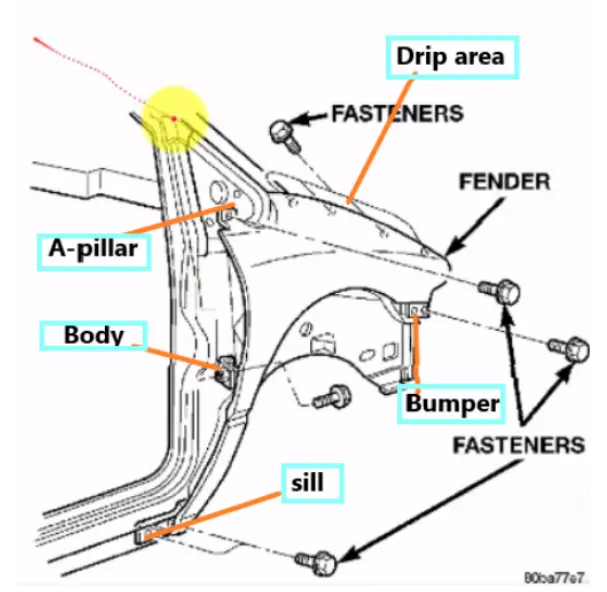
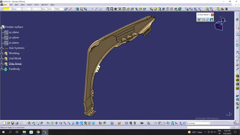
There are 5 mounting regions on the fender, they are:
- Drip Area Mounting.
- Sill Mounting.
- Bumper Mounting.
- A-Pillar Mounting.
- Baffle Mounting Area.
Design Methodology :
Given Data:
1. Design of Drip area mounting:
It is the important mounting uni of the fender.It is connected with the engine compartment, therefore a lot of design constraints are to be followed while designing the fender.
While designing the drip area we have to initially leave 200-300 mm for the cowl top for placing the headlamp we have to leave at least 150 mm at the front while designing the fender.
The cowl's top part consists of a wiper motor and its instruments.
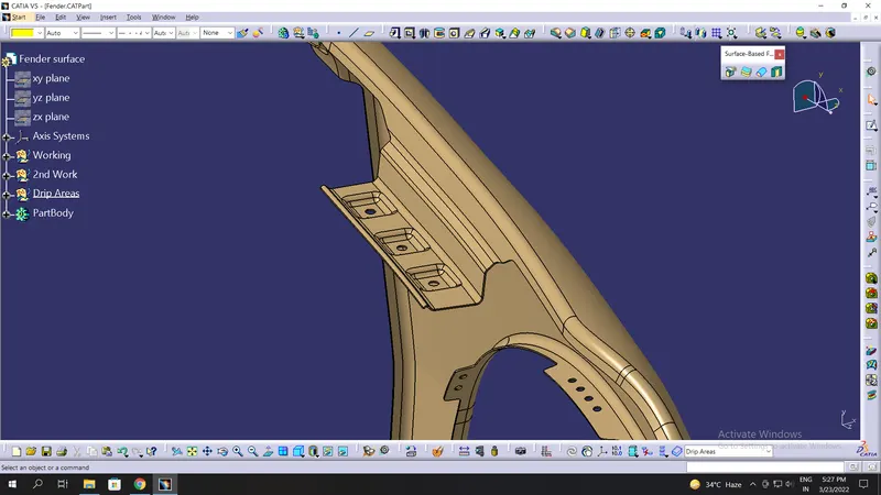
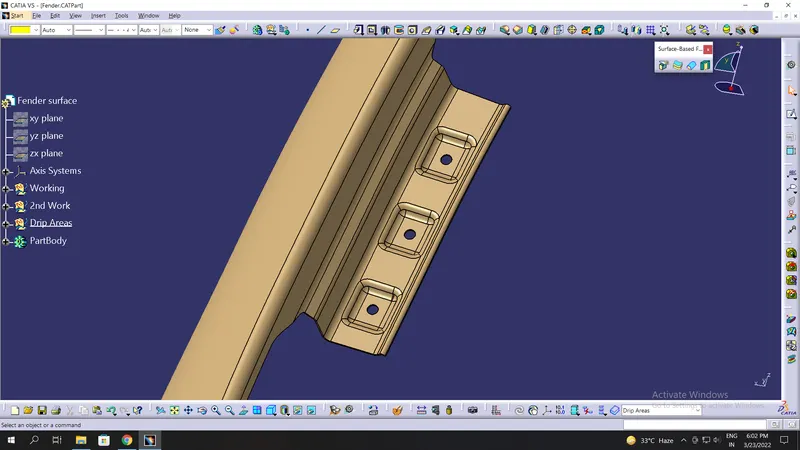
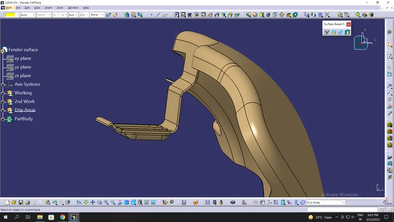
Two darts are added on the longer side of the drip area in order to provide stiffness and add strength to the part. This helps the fender to not to vibrate and impact the forces outside of the fender during the motion of the vehicle.Embossing is provided on the mounting to strengthen them during fastening.
2. Design of Sill mounting area :
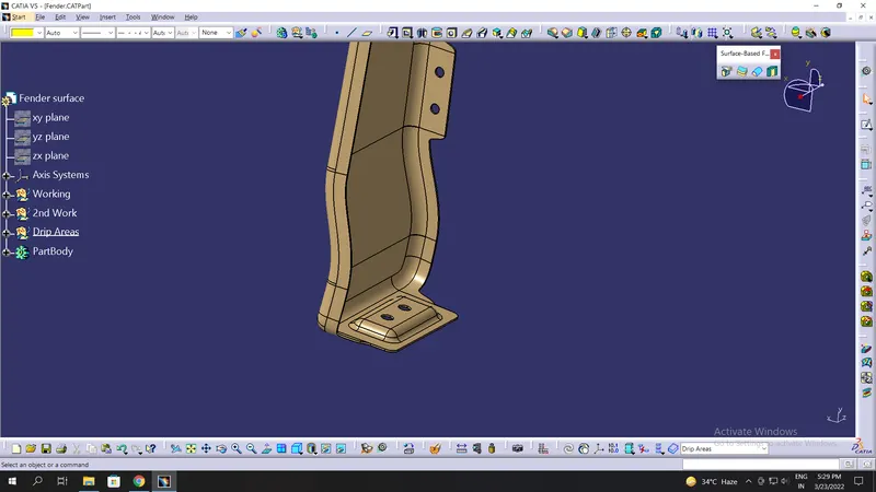
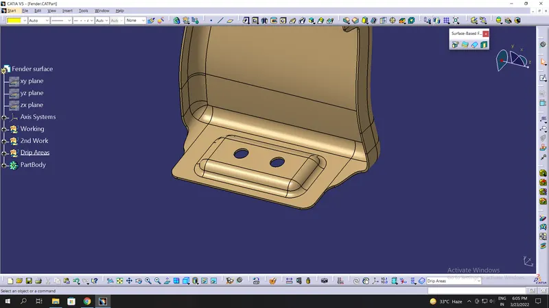
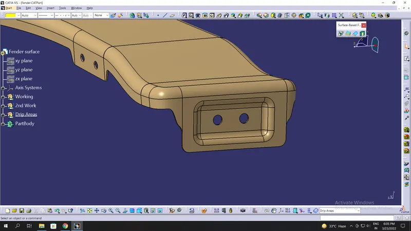
Sill is the panel directly below the bottom of the door supporting the floor and may be used to combine the floor and the body. The bottom end of the fender is mounted on the sill body for reinforcement of the fender panel, thus the sill mounting position is designed with holes and emboss.M5 fasteners are used to fix the fenders on the sill body.
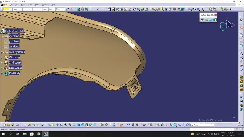
3. Design of Bumper mounting area :
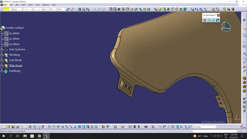
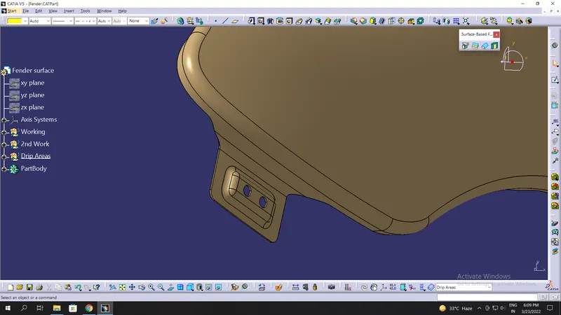
A bumper mounting area is used to fix the plastic bumper to the fender with the help of the fasteners.
4. Design of A-pillar mounting area :
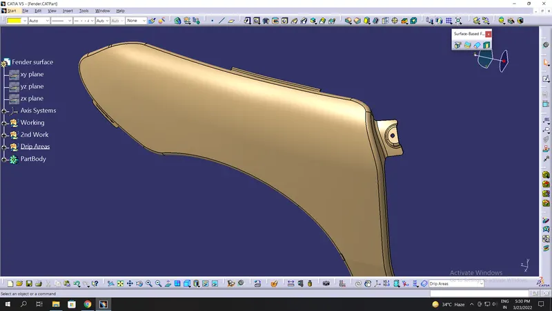
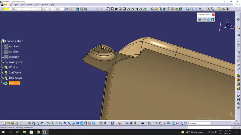
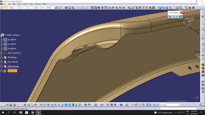
The A-pillar is the structural pillar that combines the body with the roof. this makes the sides of the windshield rest. Front fenders are fastened to the A-pillar to form a robust structure.
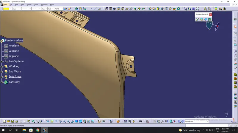
5. Design of Baffle Mounting Area:
Baffle mounting or mudguard are clip fit types of mounting on the inner side of the fender arch over the tyre. It protects the car engine compartment and pedestrians from causing injuries from chip out debris on the road when the car is in motion. They are mounted on the fender using a special type of locking clips that are made up of plastics (push-pins).
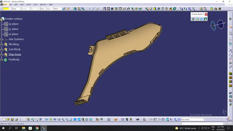
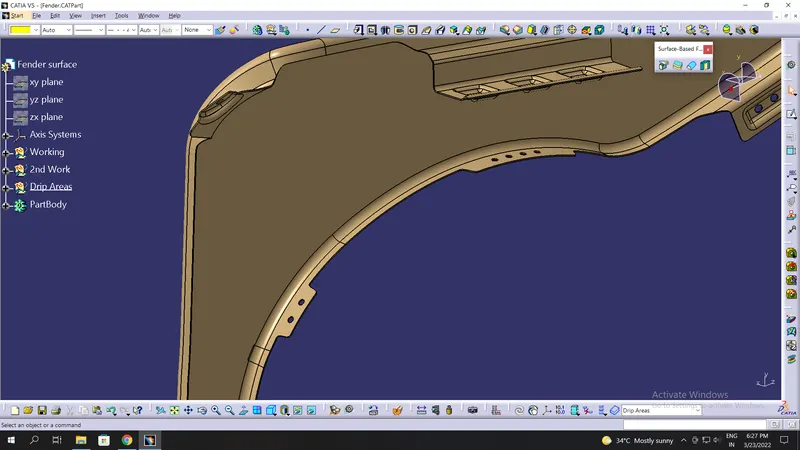
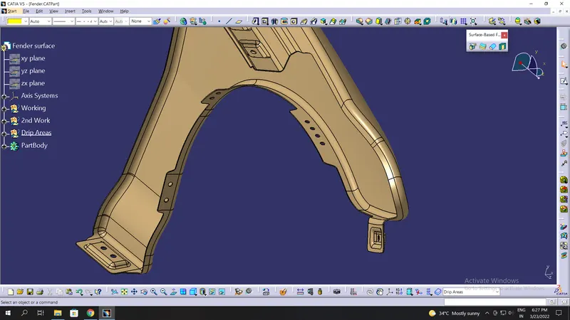
Applying of thickness to the surface :
The thickness of 0.75 mm inward on the final sewed surface of the fender to the sheet metal parameters.
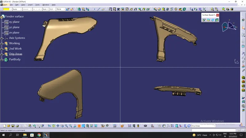
Final Component: