Fender Design Challenge
OBJECTIVE
To create the BIW of a Fender utilising the fender skin data as input data, and then attach mountings to the fender to connect it to the surrounding BIW bodies.
THEORY
The part of an automobile, motorcycle, or other vehicle body that frames a wheel well is referred to as a fender in American English (the fender underside). Its main function is to keep sand, mud, gravel, liquids, and other road spray from being flung into the air by rotating tyres. Fenders are usually rigid and can be destroyed if they come into touch with the road.
As the tyre rolls over the ground, sticky elements like mud can stick to the smooth outside tyre surface, while smooth loose objects like stones can become momentarily embedded in the tread grooves. As the tyre imparts kinetic energy to the attached objects, these materials can be expelled from the tire's surface at high speeds. The top of a moving vehicle's tyre rotates upward and forward, throwing things into the air at other vehicles or pedestrians in front of the vehicle.
TYPES OF FENDER
- Full fender type
The conventional style of fender is the whole fender, which consumes more material. This type is found in older automotive designs.
- Half fender type:
Half-fender type is a modern design that uses less material, increasing productivity by lowering the size of the blank and so delivering better performance. In comparison to full bumper types, maintenance is also comparatively low.
DIFFERENT MOUNTINGS IN THE FENDER
The fender which is designed in this project have mountings attached to it which would help the fender to fix with the adjacent components.
The mountings present on the fender are:
- A-Pillar mounting
- Drip Area
- Sill mounting
- Bumper Mounting
- Baffle Mounting
PROCEDURE
DESIGNING THE A PILLAR:
- To begin, extract the skin data provided by the style team.
- The fender's outer border was then angled inwards to a specific length.
- The undesired areas were then clipped out using the trim sheet command and the curve on surface command.
- The A-Pillar was expanded and trimmed on the sides to provide a flat edge utilising the law extension.
- A datum lane was developed to provide a flat emboss that was utilised to mount the fender with the A-Pillar.
- Then, on the datum plane, the needed sketch was produced and projected onto the surface.
- After that, the trim surface command was used to make a fastener hole with a 5mm space around it.
- Then the required blends were added using face blend and edge blend.
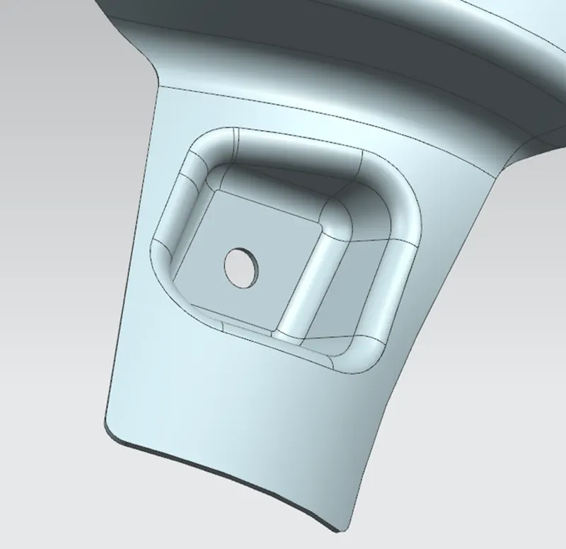
DESIGNING THE BUMPER MOUNTING:
- Using the Curve on surface and Trim surface commands, the undesired areas were clipped away.
- Then for creating a flat surfaced Emboss a datum plane was created.
- After that, the appropriate sketch was projected onto the surface and the required emboss was made.
- After embossing, the holes were trimmed with a trim sheet.
- Emboss was designed using a draught to ensure that it met the production criteria.
- Last but not least, the required mixes were applied.
DESIGNING THE DRIP MOUNTING:
- The drip mounting was generated using the information from the master section.
- The drip area must be at least 150mm away from the front edge to avoid interfering with the head lamp mountings.
- To avoid a collision with the engine wires, the drip region must be 150mm separated from the back edge when viewed from the back.
- Two planes were formed to generate the drip area at the needed distance, and then the intersection curve was used to create the required curve on the surface.
- The remaining undesired parts were then cut away.
- The design is important in preventing the human eye from looking inside the car through the space between the hood and the fender.
- As a result, the drip area in the master portion was built at a specific angle.
- The needed emboss was generated after the legislation extension was created as required by the master section.
- To create emboss, a datum plane was created, a sketch was produced in it, and the emboss feature was applied.
- Trim sheet options were then used to make the fastener holes.
- After that, the required mixes for boosting the fender's look were made.
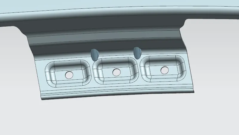
DESIGNING THE COWL MOUNTING:
- The cowl mounting was designed to accommodate a splash mounting, which protects the engine compartment from debris entering it while driving.
- Three mounting places were built for it, each with the requisite holes for the fasteners.
- A datum plane was generated on all three mountings and projected onto the surface to produce the holes.
- The holes were generated by picking the required vector and deselecting the project on both sides option.
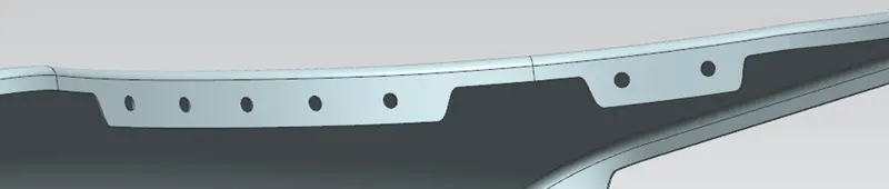
DESIGNING THE SILL MOUNTING:
- The superfluous sections of the Sill Mounting were taken out.
- After that, the datum was formed, and the appropriate drawing was drawn and projected.
- Finally, emboss was created, and the edges were blended together.
- The trim surface feature was used to make the fastener holes.
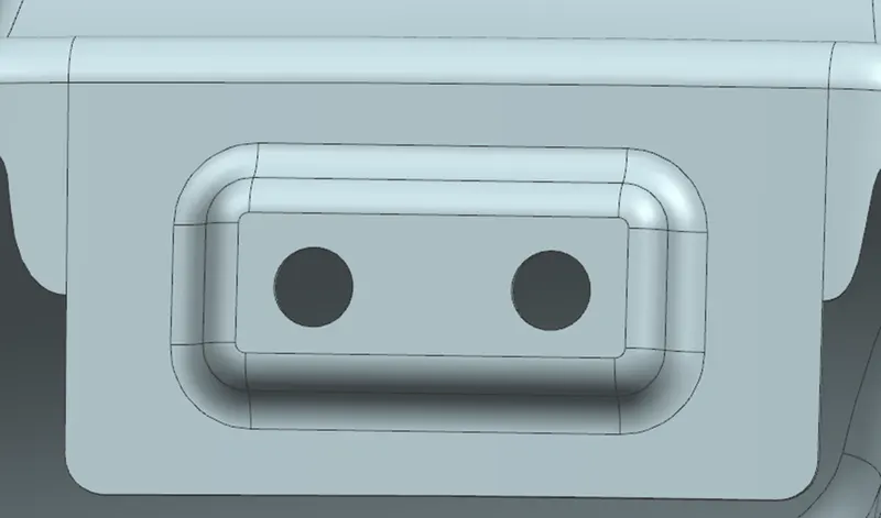
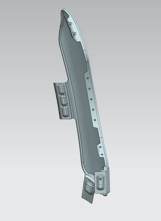
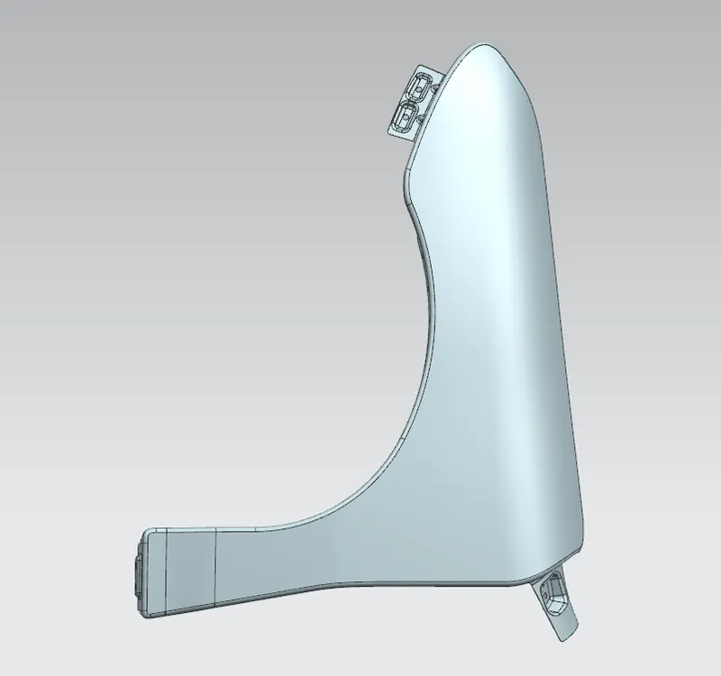
conclusion: As a result, the fender was made for the car and all mountings were installed according to the requirements.