Fender Design Challenge
TITLE: FENDER DESIGN USING SIEMENS NX.
OBJECTIVE:
The main objective of this project is to learn the basics of the BIW through designing the front fender mounting using sheet metal parameter with given skin data and master section using Siemens NX CAD.
Introduction:
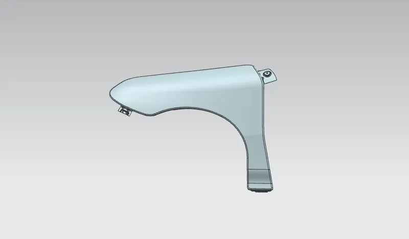
Fender is body in white part of an automobile (vehicle body) which houses or frame wheels in order to prevent sand, mud, rocks, liquid and other road debris to through into air when tires are in motion, which may lead to pedestrian accident and protect the engine compartment from damages. Apart from the pedestrian safety it serves the purpose of providing aerodynamic shape to car thus to perform better at higher speeds and give aesthetic look to body.
In current US auto industry nomenclature, usually only the panels over the front wheels are called fenders. The auto industry changed from rear fenders bolted onto a quarter panel to an enlarged welded-on quarter panel that fulfilled both functions. This resulted in one piece where there had previously been two, and name of the larger welded piece, the quarter panel, survived the consolidation. Quarter panels are at the rear, with an exception made for dual rear wheel trucks, where the panel at the rear is called a fender. For vehicles with a narrow car body that exposes the tire, the fender is an exposed curve over the top of the tire. For wide body vehicles that cover the tire, the fender forms the wheel well surrounding the tire, and is not directly visible from above the car body.

Types of Fender:
Fender can be designed in two ways. Half bumper type and Full bumper type.
Full bumper Type:
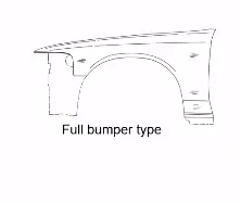
Full bumper type is traditional type of fender where more surface area covered. This type is used in old design of automobiles where it increases the overall weight and thus reduces performance.
Half Bumper Type:
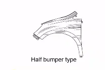
Half bumper type is modern design which serve the technical requirement of full fender using less material. In the case of a half bumper type we have the high possibility to reduce the scrap this is called scrap management. As the material consumption to produce the part is low result in reduction in overall weight of steel body thus increase the performance, also reduces manufacturing cost thus, we can provide better fender with cheaper price to the customer.
Design Methodology:
given data:
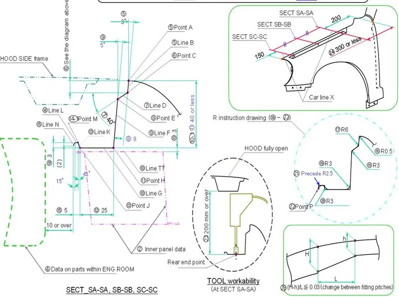
master section
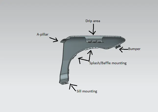
Apart from the aesthetic area of the front fender. It required 5 different mounting to be designed through which the fender can be joined to the vehicle, by taking industry constraints in mind they have to design.
Five different mountings area are:
- A-pillar mounting area
- Drip mounting area
- Sill mounting area
- Bumper mounting area
- Body mounting area
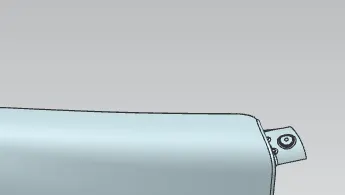
- A-Pillar mounting
A pillar mounting is the area where the fender attaches the a-pillar using fasteners.
Here I have created a 25 mm length flange and I have created one emboss having a plane as end cap for achieving the flat surface for the fasteners. I have also maintained 5 mm flat surface around the holes.
Here the hole radius is 6mm and I have drawn a circle of radius a 14 mm concentric to the hole, shows a flat surface of more than 5 mm is there around the hole.
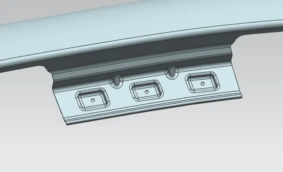
- Drip area
Drip area is the mounting of the fender which mounts the fender to the engine compartment. The drip area is usually in between the head light housing and the cowl top. Thus, for designing the drip area we have to consider some constraints:
- The first factor to consider is the distance of the drip from the A pillar mounting. As shown in master sketch, the distance from the cowl top area to the drip must be 200 mm or more as in that region viper motor and other mounting will be mounted. But in some cases, as the size of the cowl top area decreases this distance also decreases.
- Similarly, from the front end of the fender we have to leave 150 mm space for the headlight housing.
- Hood side drip depth must be 40 mm or less as maximum productivity is achieved at the depth of 40mm. if depth exceeds 40mm then rigidity bead is to be provided. Also forming is not feasible if depth exceeds 60 mm due to wrinkling and spring back.
- The side endmost part of the drip area should be 10mm away from the engine compartment part so that assembly of the fender will be smooth.
- To prevent fender fixation bolts to be seen from outside and improve the appearance of parting gap between hood and the front fender, adequate angles are provided.
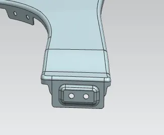
- Sill mounting
Sill mounting is another mounting in the fender which attaches the sill to the fender using the fasteners. Same as the A-pillar mounting, I have created a flange of 25mm length and made 1 emboss with flat surfaces and also 5mm flat surface around the hole is maintained.
- Bumper mounting
The part which attaches the bumper to the fender consideration for bumper mounting is same as the sill and A-pillar mounting.
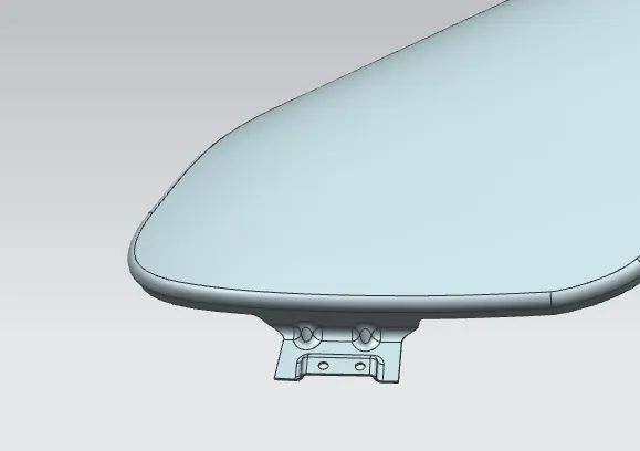
- Baffle mounting
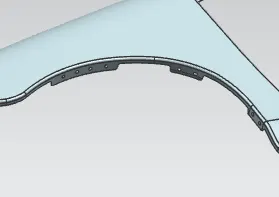
baffle mounting or mudguard are clip fit type of mounting on the inner side of the fender arch area over the tire. it protects the car engine compartment and waking by pedestrian from causing injuries from chip out debris on road when car is in motion. they are mounted on the fender using special type of locking clips which are made up of plastics eight mounting holes with surface resting projection of 5mm are provided over the arch area to give maximum strength to baffle during its fitting.
Different views of front fender:
isometric view:
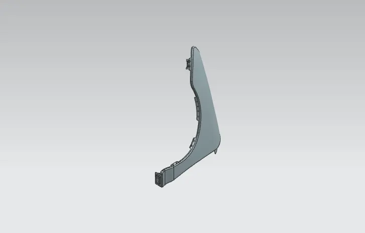
Front view:
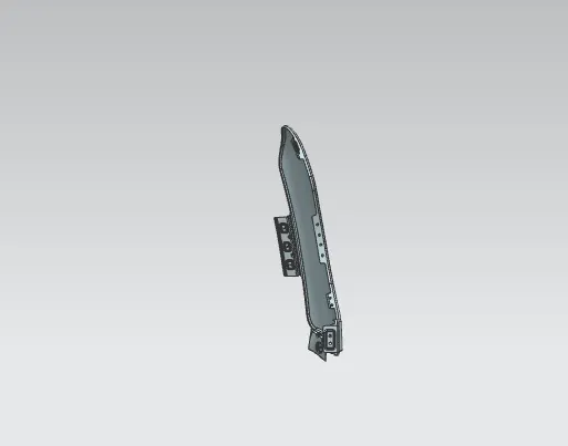
Top View:
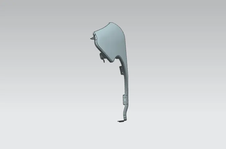
Right View:
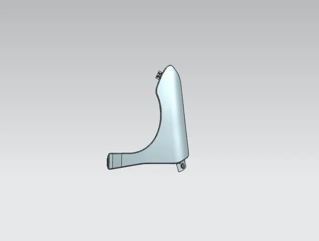
Conclusion:
the fender and its all mountings has been successfully created by considering all the standards and parameters of BIW fender design.