Fender Design Challenge
FENDER DESIGN:
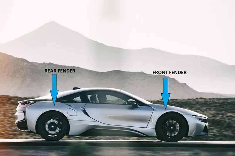
Fender is a part of an automobile that frames the wheel well. It's primary purpose is to prevent sand, mud, rocks, liquids and other road spray from being thrown into the air by the rotating tire.
When vehicle is moving tires pick up stones and other substances present on the road and hurl them in all directions. Fendeers are basically present to prevent any injuries to the pedestrian and contain the contain of these particles.
Most passenger automobiles have four fenders, one over each wheel.
For vehicles with narrow body that exposes the tire, the fendder is an exposed curve over the top of the tire.
For vehicles with wide body that covers the tire, the fenders form the wheel well surrounding the tire and is not directly visible from above the car body.
FULL BUMPER TYPE:
HALF BUMPER TYPE:

MOUNTINGS:
The important mountings that are present in a fender are:
1. Drip
2. Body / A-Pillar
3. Sill
4. Cowl
5. Bumper
According to the requirement of the automobile the mountings are designed so that the fender gets fixed properly.
IN THE ABOVE ASSIGNMENT WE ARE GOING TO DESIGN DIFFERENT MOUNTINGS OF FRONT FENDER HALF BUMPER TYPE.
FRONT FENDER
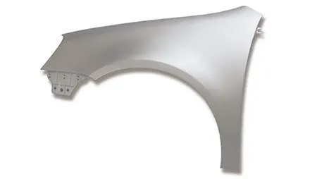
DESIGN PARAMETERS :
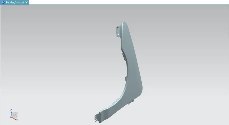
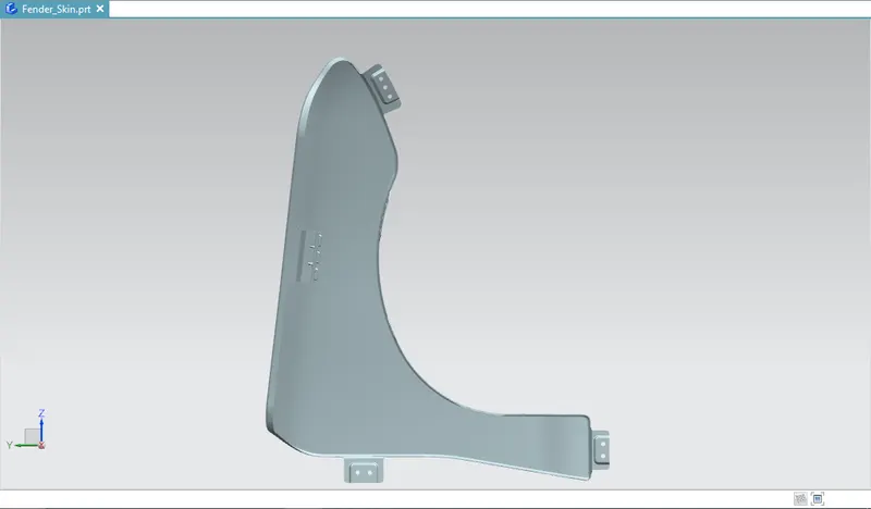
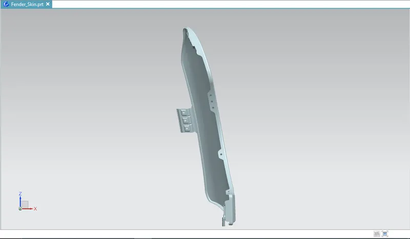
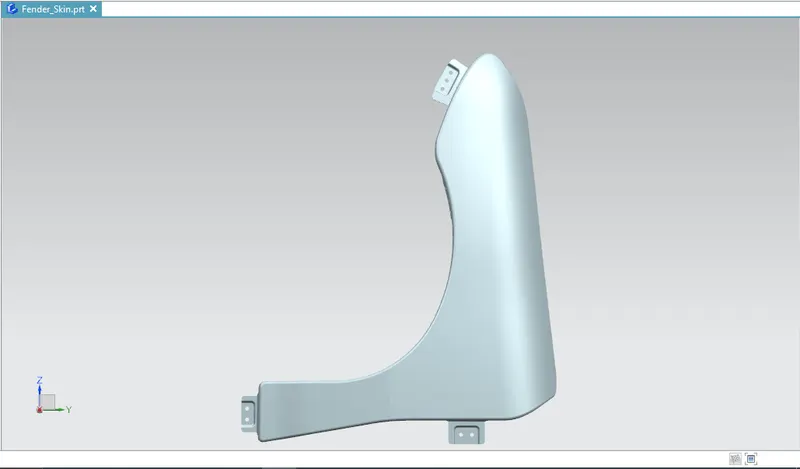
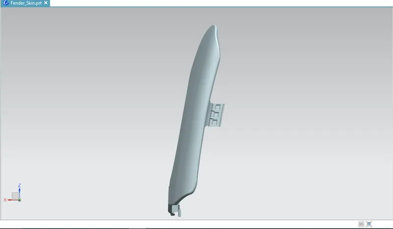
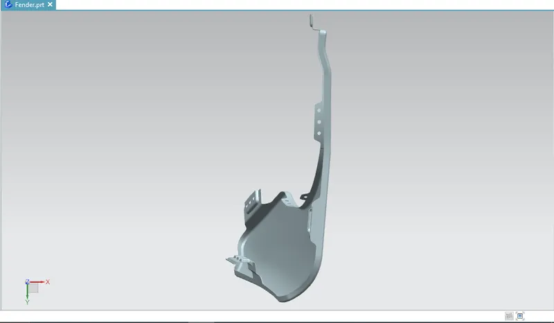
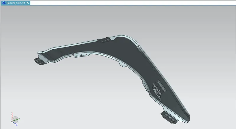
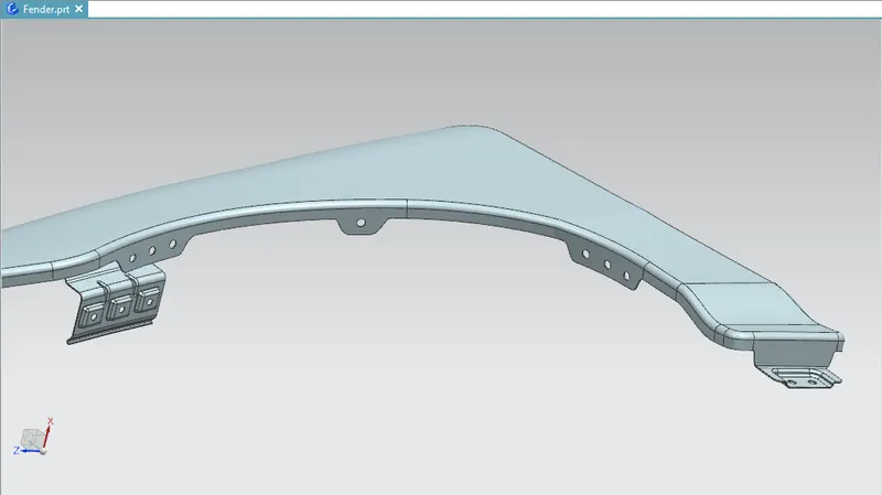
We need to design different mountings of the front fender from the skin data given.
1. DRIP MOUNTING:
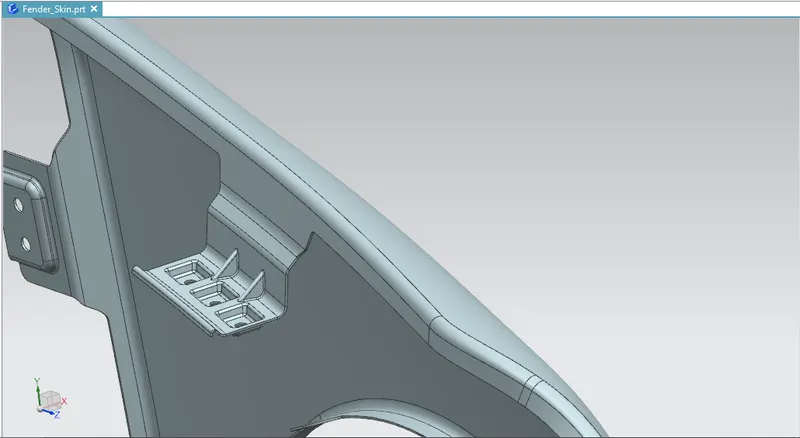
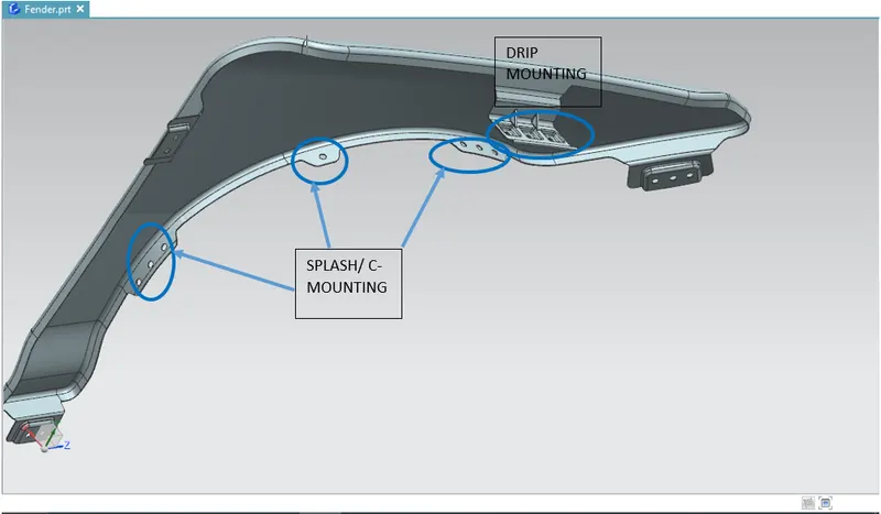
This is the most important mounting part in the fender. It must be designed in such a way that it does not give any spring back effect, there must be clearance for headlight mounting and windscreen.
This mounting is given to mount the fender to the engine compartment area and also we need to keep in mind about the strength of the mounting.
This can be designed from the master section provided:
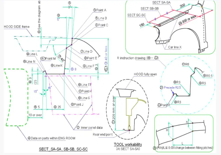
1. A clearance of 150mm is given for the headlight mounting and a clearance of 200mm is given for the mounting the cowl.
2. The end most part of the drip area must have a clearance of 10mm between the Engine room.
3. Embosses are provided for better strength and the embossed faces must be flat surface to rest the face in the engine compartment.
4. Darts or Ribs are provided in order to increase the strength of the mounting and to arrest the spring back motion ass only one-side is fixed.
5. The total length of the drip mounting should be less than 40mm to avoid the spring back effect.
6. A tool landing area of Radii 5mm should be there in order to cut the hole from the sheet.
7. There should not be any sharp corners or edges.
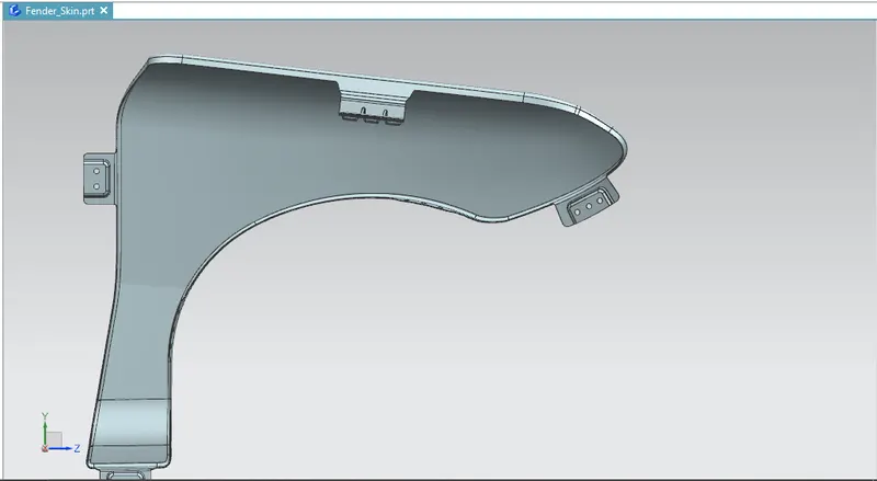
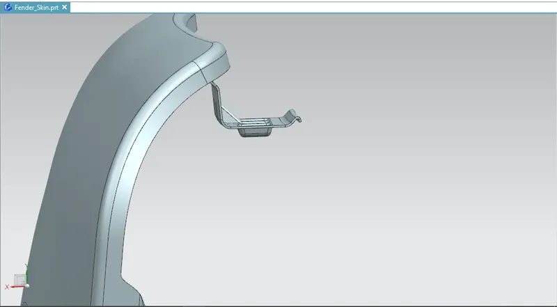
2. BUMPER MOUNTING:
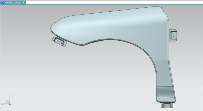
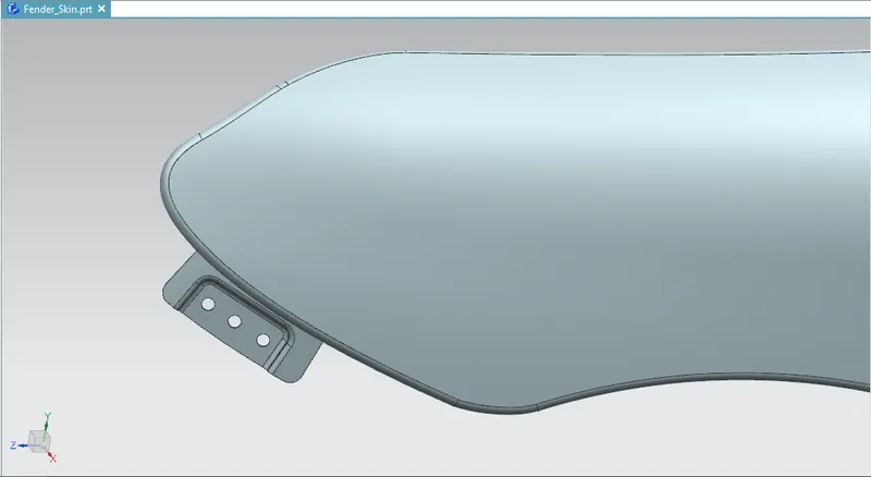
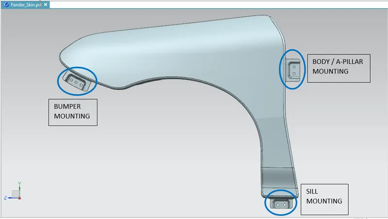
This mounting is provided in-order to mount the fender to the bumper of the vehicle.
1. Embosses are given to increase the strength of the mounting area and the embossed surface must be a flat face in order to rest the face properly on the bumper.
2. There must be a tool landing area of Radii 5mm in order to cut the hole from the sheet.
3. There should not be any sharp corners or edges.
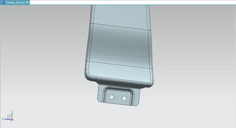
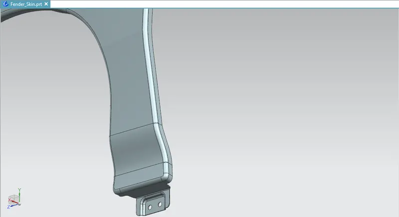
3. SILL MOUNTING:
The mounting is provided to mount the fender with the Sill of the vehicle.
1. Embosses are given to increase the strength of the mounting area and the embossed surface must be a flat face in order to rest the face properly on the bumper.
2. There must be a tool landing area of Radii 5mm in order to cut the hole from the sheet.
3. There should not be any sharp corners or edges.
4. A-PILLAR / BODY MOUNTING:
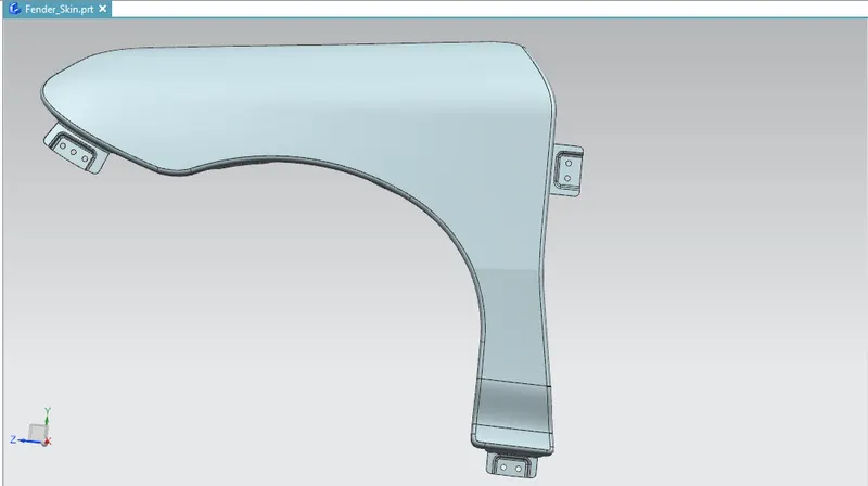
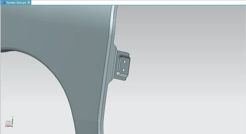
The mounting is provided to mount the fender with the Body or the A-pillar of the vehicle.
1. Embosses are given to increase the strength of the mounting area and the embossed surface must be a flat face in order to rest the face properly on the bumper.
2. There must be a tool landing area of Radii 5mm in order to cut the hole from the sheet.
3. There should not be any sharp corners or edges.
5. SPLASH / C- MOUNTING:
This mounting is provided to mount the Baffle which is a NVH component.
1. As only Rubber like material has to be mounted in this area to arrest the Vibration and Noise so much strength is not required so embosses in this region are not necessary.
2. Only we have to provide holes for the push clips to fix the baffle.
3. There must be a tool landing area of Radii 5mm in order to cut the hole from the sheet.
4. There should not be any sharp corners or edges.
MARKINGS:
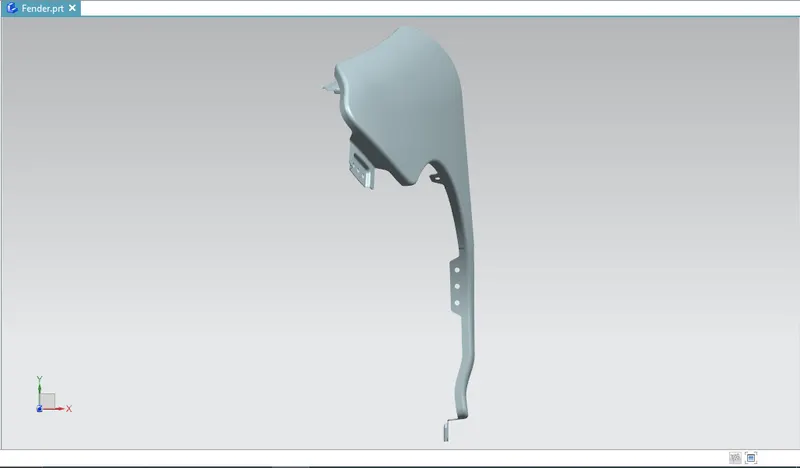
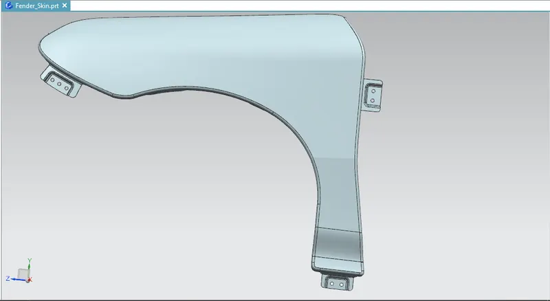
FINAL MODEL OF FRONT FENDER