Fender Design Challenge
FR- FENDER DESIGN
OBJECTIVE
- To complete the front fender design using the given styling surface and to design drip area based on the given master section.
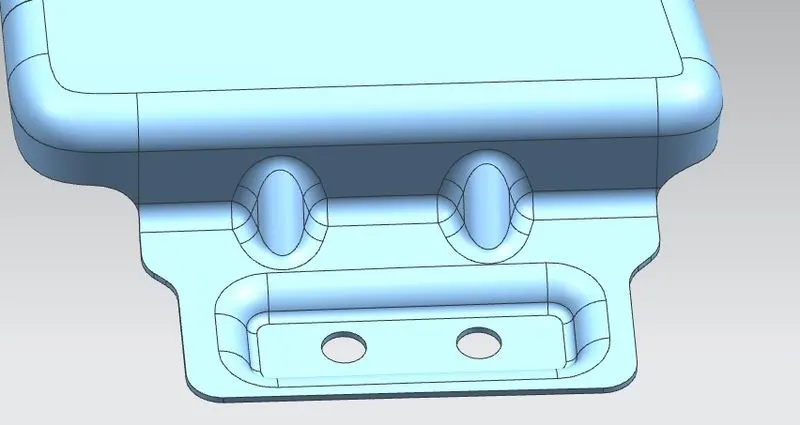
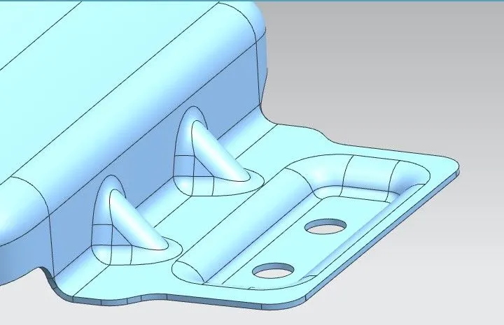
- To provide various mounting flanges in the fender such as Sill mount, A-pillar mount, Bumper mount, splash mount and drip area as well.
Introduction
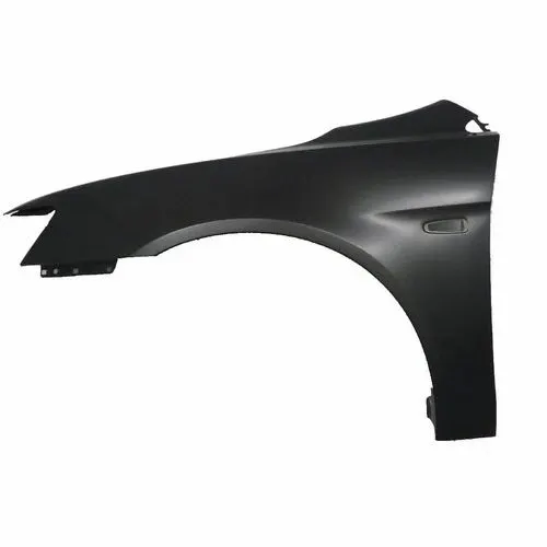
- Fender or Quarter panel is a BIW component of an automobile (vehicle body of car) that frames the wheel well (the fender underside). Its primary purpose is to shield wheels and protect both passenger's compartment and pedestrians from projection of water, mud and stones.
- Fenders are typically rigid and can be damaged by contact with the road surface.
- These panels are mainly called fenders because they are used to literally fend off the attack of all kinds of road debris.
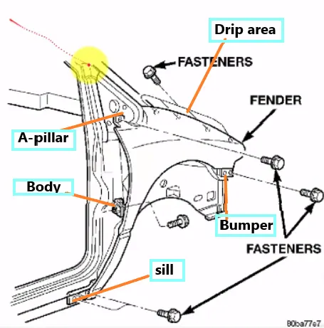
Fig shows: Various mounting positions of fender
Wheel Arch:
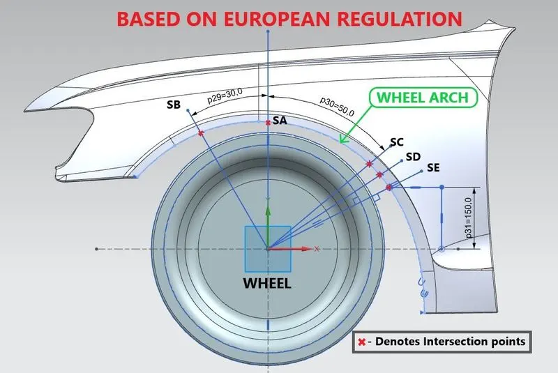
Fig shows: Wheel arch design based on European regulation standards
- It is the semi-circular part of the fender positioned above the wheel of the vehicle.
- It is the shaped part of the bodywork of a car or other vehicle that allows the wheel to be accessed, and in the case of front wheels, enable them to be steered.
- It must be designed such that it covers or shields over the tyre along the perimeter to prevent stones,debris,mud,water,snow,or other foreign substances from getting thrown into the vehicle/BIW components as well as outside the vehicle onto other vehicles or the pedestrians on the road.
- Generally European Regulation standards are used for the wide acceptance of the wheel arch design.
Types of Fender:
- Full front or Full Bumper fender- This type covers the tyre and the forms the wheel well surrounding the tyre and is not directly visible from above the car body. This is quite heavy and consumes more materials and scrap. To overcome this, half front fender is used widely.
- Half front or half Bumper fender- This type of fender reduces the scrap and weight of the vehicle comparatively thus leads to increase in the mileage of the vehicle.
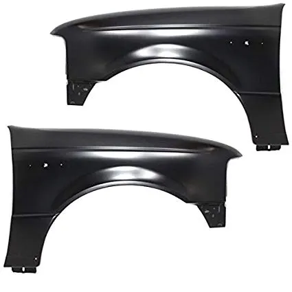
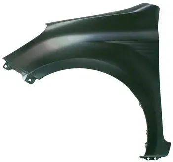
Fig shows: Full Front Fender Fig shows: Half front fender
Process of Fender Repairs
The usual fender repairs done by the car technicians can take care of cracks or breaks and dents. Here are the usual fender repairs that they perform:
1. Repairing Cracks or Breaks
Before the repair technician starts the repair, they will first examine the extent of the damage. If that section can be filled and reinforced, it will be the first thing that they will do. It is similar to filling a big scratch with fillers. Buffing will follow after the filler has dried. And then that section will be painted over with the same car color or the owner’s choice.
But if the damage is big, the damaged fender should be replaced. The reason is that the fender needs to have a structural integrity that can help it fulfill its primary function.
2. Repairing Dents
The process of pulling out can repair dents on fenders. There are different ways to pull out dents:
- One way is by suctioning the dented part;
- Pound or hammer it to its former surface level; and
- A third way is to fill out the dent with fillers.
The latter two are not recommended. Car repair technicians usually perform the suction process. They use a big unit that looks like a vacuum hose to suck out the dent. If the dent does not move, you may need to replace the entire fender panel.
3. Scratch Repairs
Scratches are the most common damage inflicted on fenders. There are two ways that you can do this kind of repair. You can buff out minor scratches and paint over the section to look the same as the colors of the other sections. For deeper scratches, you have to fill the gaps with putty or filler, and once it completely dries, buff that part and paint it over.
Considerations for Fender design:
- Safety of the passengers
- Safety of pedestrians
- Sealing the engine bay and other vehicle components
- Styling and aesthetics of the body
- Aerodynamics of the body structure
- Energy absorption during collision
- Crash safety
- Mounting flanges and clearances
Assembly:
- The fender is usually assembled with the other BIW component of the vehicle using Nuts and bolts, screws and other fasteners instead of welding or adhesives.
- The fasteners are preferred since when the complete assembly of all the Panels are done the mounting points of the fender will be completely out of sight so that the nuts or bolts are not visible from outside. And it makes ease of services and replacements.
- The fender has nearly 4 or 5 mounting points to reduce the vibrations and noise from the engine compartment to the passengers compartment or outside the vehicle.
- Some fenders are provided with air vent to reduce the heat in the engine bay.
- Mounting positions of fender-
- Drip area (fixed with engine compartment)
- A-pillar mounting
- Sill mounting (Lower-side component of chasis)
- Bumper mounting
- Splash shield mount
- Side door mount (Not really provided in modern cars)
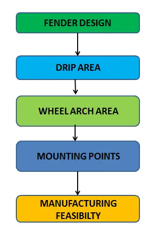
Fig shows: Fender design methodology
Design methodology:
Master section provided-
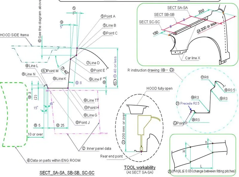
Fig shows: the master section/data provided
Styling surface:
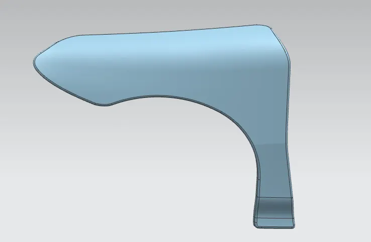
Fig shows: Given Skin data
Standard data from the master section:
- The top most edge of the fender should have a defined clearance between the hood and the fender.
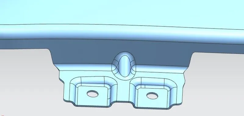
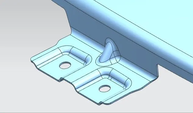
- Embosses has to be provided for mounting projections with flat surface.
- Providing necessary relief cuts and fillets at sharp edges to prevent the stress concentration at specific corners.
- Darts are provide to increase the strength of the mounting flanges and to reduce the spring back effect of fender.
- The holes are positioned with minimum of 5mm surface around the hole and it must be drilled with respect to the vectors of X/Y/Z.
- Springback effect- is the geometric change made to a part at the end of the forming process when the part has been released from the forces of the forming tool.
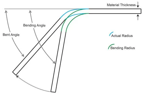
Fig shows: Springback effect in sheet metal
Fender design:
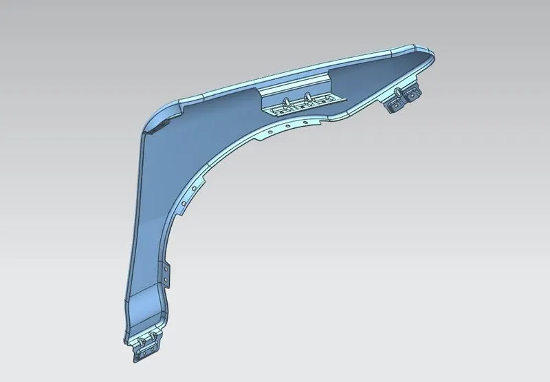
Fig shows: Isometric view of fender
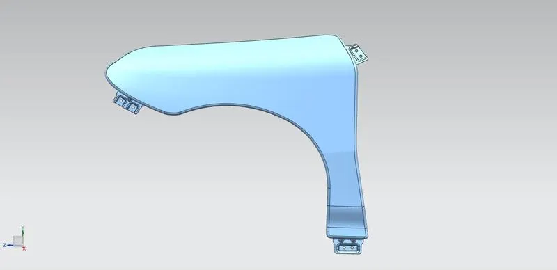
Fig shows: FRont view
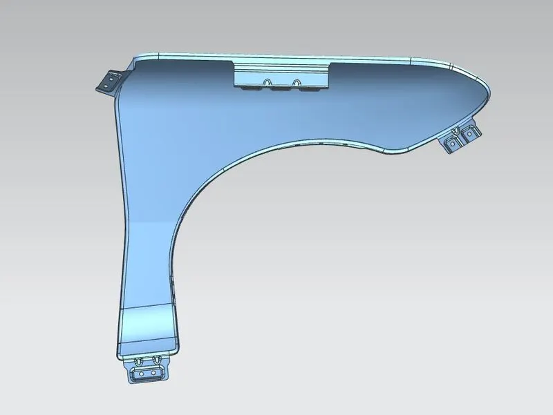
Fig shows: Back view
Mounting areas in Fender design:
1. Drip area:
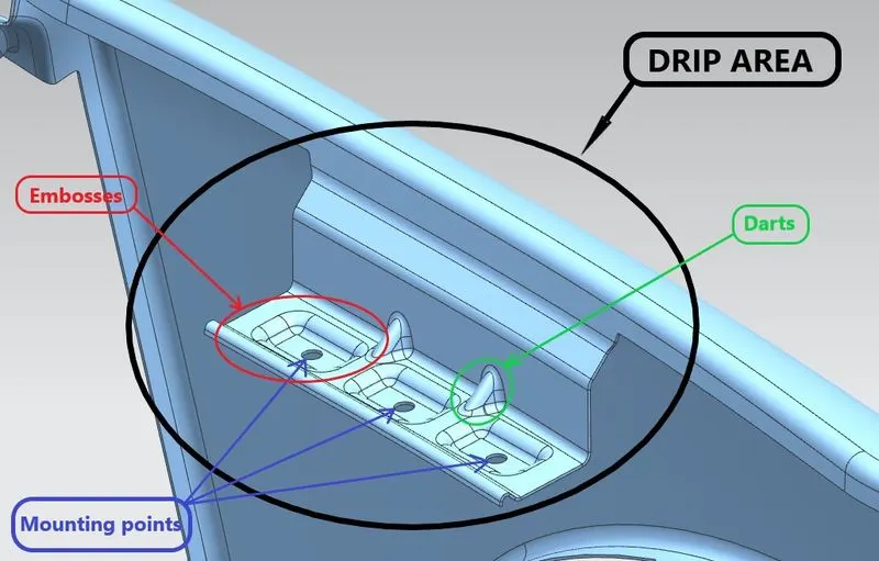
Fig shows: Drip area
- It is the area through which fender is attached to engine housing through fasteners.
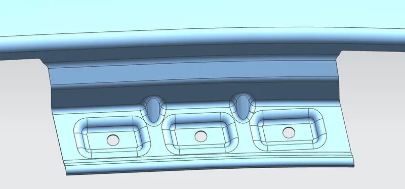
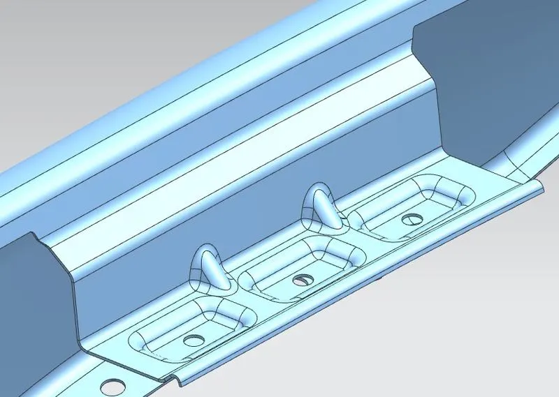
- There are 3 mounting points provided in the drip area design.
- There should be some consideration followed to design the drip area of fender. From back side of front fender, there will be 150mm clearance for cowl(wiper motor) mounting area. This clearance must not exceed 300mm.
- A 150mm gap must be provided from the front of the fender for the head lamp housing unit. The drip area will lie between these 2 limitations as recquired.
- In the fender, over a period of time the drip area will be subjected to deformation in geometry due to the vibrations in the engine as a result of springback effect. To prevent this darts are provided.
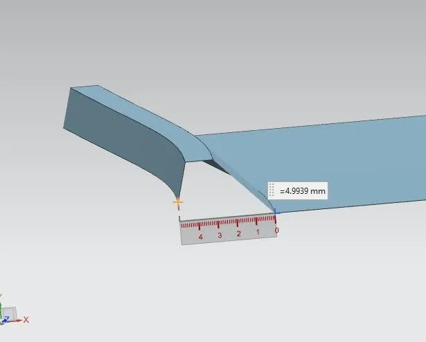
- As per the master section data, the minimum clearance between the drip and the other component of the engine is achieved by maintaining the outermost edge within 5mm from its neighbour edge. This geometry also controls the wobbling motion of the flange.
- Design calculations:
1.) To find 'a' -
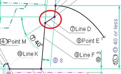
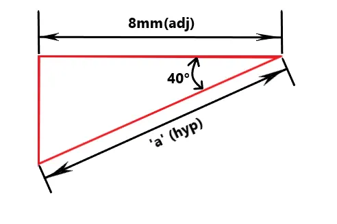
Fig shows: location of the target geometry
Solution:
adj= 8mm
angle(`theta`)= 40°
a=?
`costheta`= `(Adj)/(Hyp)`
`cos40^@`= `8/a`
0.766 = `8/a`
a = `8/0.766`
a = 10.44m
2.) To find "a,b,c,d&e"-
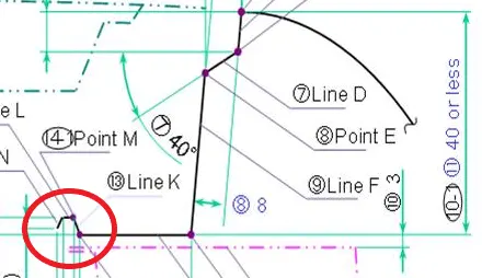

Fig shows: Dimensions to be found based on master section
Solution:
- The values might be rounded up to the nearest value for manufacturing constraints in production.
i.) a&b,
`costheta = (Adj)/(Hyp)`
`cos45^@ = 3/a`
`0.707 = 3/a`
`a = 3/0.707`
`a = 4.24mm`
`tantheta= (Opp)/(Adj)`
`tan45^@ = b/3`
`b = 1xx3`
`b = 3mm`
ii.) c&d,
`costheta = (Adj)/(Hyp)`
`cos15^@ = 2/c`
`0.966 = 2/c`
`c = 2/0.966`
`c = 2.07mm`
`tantheta = (Opp)/(Adj)`
`tan15^@ = d/2`
`0.268 = d/2`
`d = 2xx0.268`
`d = 0.54mm`
iii.) e,
`e = 5-(b+d)`
`e = 5-(3+0.54)`
`e = 1.46mm`
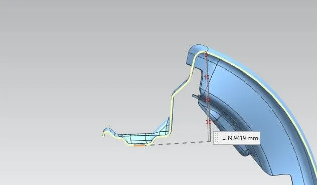
Fig shows: Cross section view of fender drip area (SEC: A-A,B-B & C-C)
- The lower most surface of the drip must not exceed 40mm measured perpendicular from the top edge of fender as shown in the above fig. This constraint is provide to avoid the springback effect in the drip area and the darts are also provided for this purpose.
- Thus the drip area is designed as per the master section provided.
2. Design of Sill mount:
3. Design of A-Pillar mount:
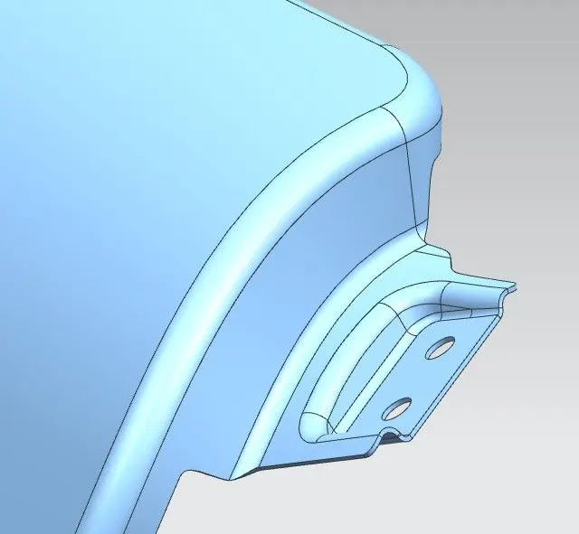
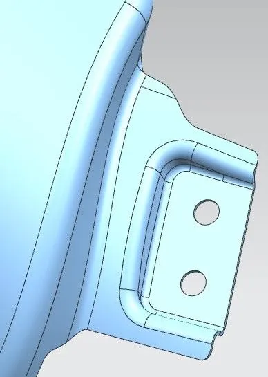
4. Design of Bumper mount:
5. Splash shield/baffle mount:
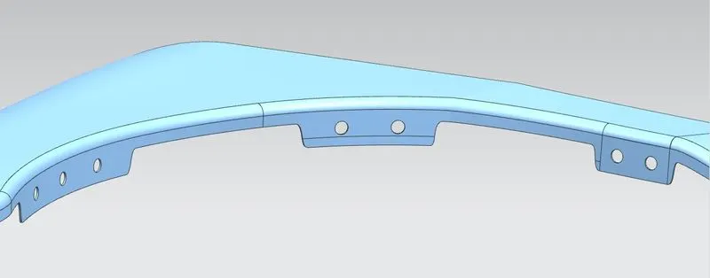
- A baffle or plastic guard(splash shield) is mounted in the wheel arch area to form the wheel well and protects the vehicle from outside debrises. This performs the ultimate function of the Fender and is most vulnerable for damage among the fender parts.
- For better life and function of fender, it is adviced to replace the damaged baffle whenever necessary.
- Necessary holes are provided for baffle mounting in the wheel well.
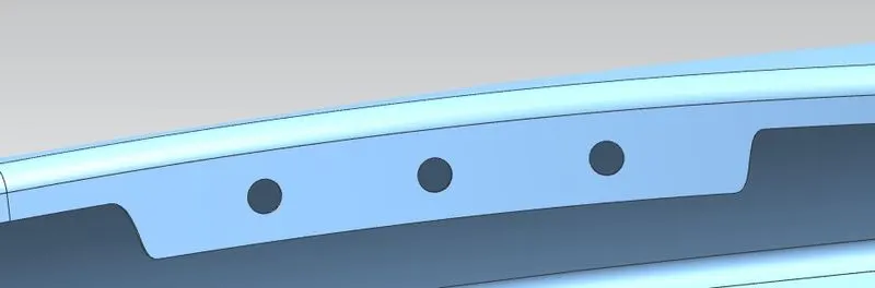
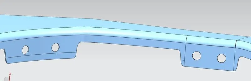
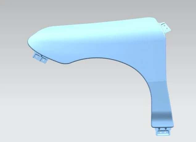
Fig shows: Shaded view of fender
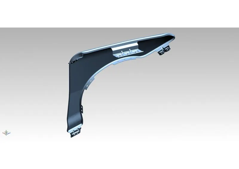
Fig shows: Rendered view of fender
Conclusion:
Thus the fender is designed using the given styling surface and all the necessary mounting areas are provided based on the master section given with standard data.