Fender Design Challenge
FENDER DESIGN CHALENGE
Aim:
The main aim is to design the fender model with the necessary mounts using the class- A surface.
Mounts:
- Bumper
- A-pillar
- Sill
- Cowl
- Drip
Theory
Fender:
A fender is a part of automobile that frames a wheel well (Fender underside). Its priamry purpose to prevent from sand, mud, rocks, liquid and other road sprays from being thrown into the air by the rotating tire. the fender opening for the wheel wells tend to be much larger than the diameter of the tire becausethey do not move with the tire suspension and consequently must be large enough to allow the full range of tire motion on the suspension without touching the interior of the wheel well.
Types of fender
Full front fender
If the fender covor the tyre, the wheel well surrounding the tire and it is not directly visible from above the car body. It increase the wieght and scrap of the component.
Half Front fender
It reduse the weight and scrap. It creates only half of what the full fender does and the other part is created with the bumper part.
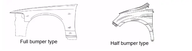
SKIN DATA AND ASTER SKETCH
Design the A Pillar
- First the skin data provided by the styling team needs to be extracted.
- Then the outer edge of the fender was offset inwards to particular length.
- Then by using the curve on surface command the unwanted portion were trimmed out using trim sheet.
- By using the law extension, the A pillar were extended and trimmed on the sides to get a flat edge.
- For creating a flat emboss which was used to mount the fender with the A-pillar a datum plane was created.
- Then the required sketch was drawn on the datum plane and projected to the surface.
- Then for creating a fastener hole which needs to be around 5 mm gap around it trim surface command were used.
- Then the required blends were added using face blend and edge blend.
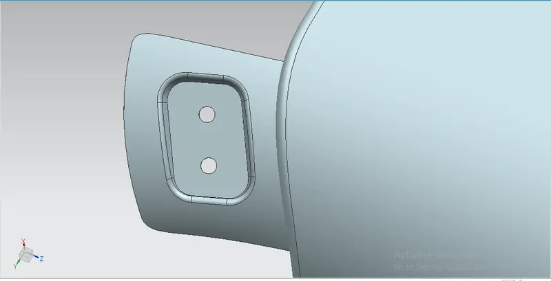
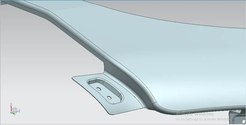
Design Bumper mounting
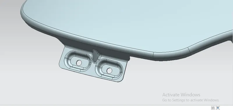
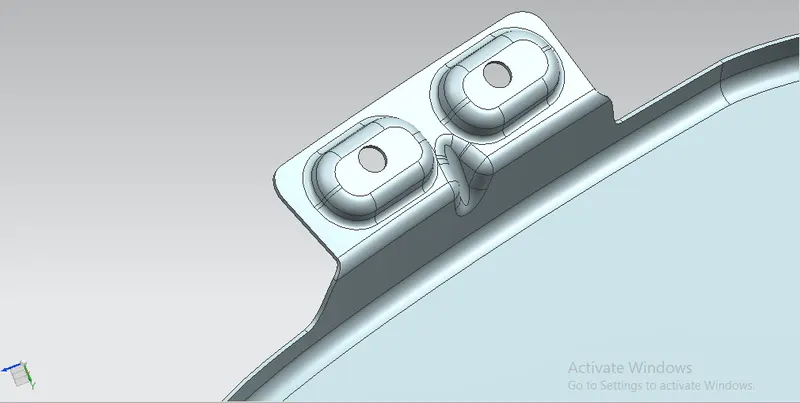
- The unwanted portions were trimmed off using curve on surface and trim surface command.
- Then for creating a flat surface emboss a datum plane was created.
- Then the required sketch drawn on the datum plane was projected to the surface and the required emboss were created.
- The holes were trimmed by using trim sheet after creating emboss.
- Emboss were created with a draft so that it satisfies the manufacturing requirements.
- Finally, the required blends were applied.
Design the baffle mountings.
- The baffle mounting was designed to fit a splash mounting on it which helps the engine compartment to protect it from.
- the debris that entering in to while driving.
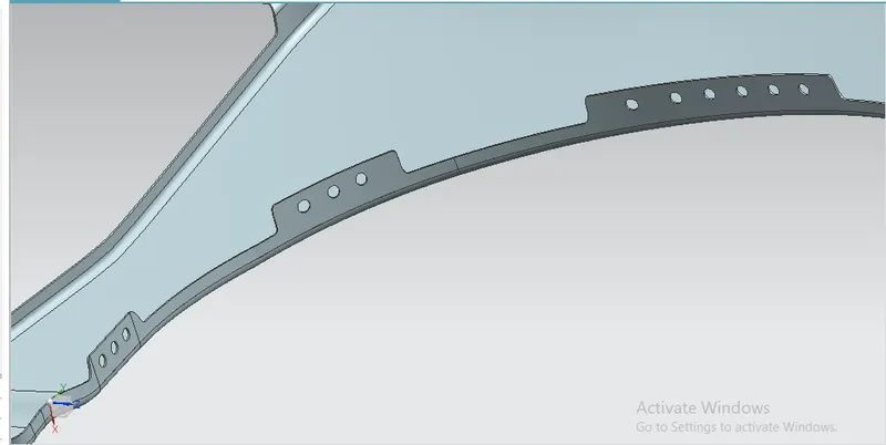
- For creating it three mounting areas were created with the required holes on it for the fasteners.
- For creating the holes, a datum plane was created on all three mountings and projected on to the surface.
- By selecting the required vector and deselecting the project on both side option the holes were created.
Design the drip area mounting
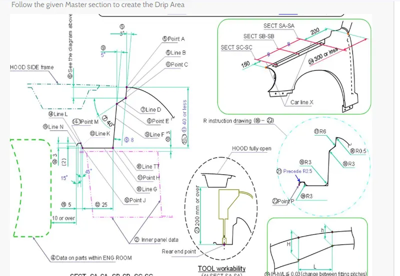
- By using the information in the master section provided the drip mounting were created.
- The drip area must be minimum 150 mm apart from the front edge so that the drip mounting won’t disturb the head lamp mountings.
- From backwards the drip area must be 200 mm apart from back edge to avoid the coincidence with the engine cables.
- For creating the drip area at the required distance two planes were created and then the intersection curve was used to create the curve on surface as required.
- Then the remaining unwanted portions were trimmed out.
The design takes a vital role in avoiding the human eye seeing the insides of the car through the gap between the hood and fender. - So the drip areawas created in particular angle as required by the master section the required emboss were created.
- After creating the law extension as required by the master section the required emboss were created.
- For creating emboss a datum plane was generated and the sketch drawn in it was projected and the emboss feature were applied.
- Then for creating the fastener holes the trim sheet options were used.
- Then the required blends were created for improving the aesthetic of the fender.
- Since the drip area was longer without any support it increases the NVH while driving so to reduce the NVH effect while driving the drip area must be strengthened.
PROCEDURE:
1. Creating the Section
- After opening the file, check the model and create the mount area Layout.
- Use parallel curve option to offset the line 5 mm and split option cut the area for the mountion.
- Now, join the split surface excluding the top surface.
2. Creating the Mount Part
- to craete the mount region use the sweep option near the space created for the mounting.
- After sweep is done as per the design model given, join the surface craeted.
3. Creating the embosses and relief
- After the mounts are created we need to create the embosses and holes are to be given.
- To craete emboss create sketch with the required shape. Project the sketch into the mounting area but before that extract the surface.
- Now, split the surface to create a hole near the projected area to crate emboss.
- Use the sweep command near the cut section. Now, offset the extracted surface.
- trim the surface together and create a relief hole which is given to such that the screw is filled into that hole.
- For the drip Mount part foloow the given detain as given.
- To create beaks create the surface in a way that is angular and then trim the suface together.
4. Giving the Fillets
- Once the suface is trimmed give the fillet near the embosses and bends.
- Use the Extrude command followed by the edge fillet to create the sharp edge to the curved parts near the mounting.
5. Creating the Solid
- After the surface is created go to the part workbench and define the part body.
- Use the thick surface option to create the solid with a thickness od 1mm.