Fender Design Challenge
DESIGN & DEVELOPMENT OF FRONT FENDER FROM THE GIVEN SKIN DATA
Introduction:
- Fender is the American English term for the part of an automobile, motorcycle, or other vehicle body that frames a wheel well (the fender underside).
- A fender is the curved portion of the car’s body that sits over and houses the wheels. Its primary purpose is to prevent sand, mud, rocks, liquids, and other roads spray from being thrown into the air by the rotating tire.
- The fender not only protects your car from sustaining damage from road debris but it prevents this debris from being thrown up at other vehicles and the pedestrians on the road.
- Most automobiles have four fenders, one over each wheel. But now only the panels over the front wheels are called fenders. The rear fender is now an integral part of the body itself.
- The fender's openings for the wheel wells tend to be much larger than the diameter of the tire because they do not move with the tire suspension and consequently must be large enough to allow the full range of tire motion on the suspension without touching the interior of the wheel well.
- For vehicles with a narrow car body that exposes the tire, the fender is an exposed curve over the top of the tire. For wide body vehicles that cover the tire, the fender forms the wheel well surrounding the tire and is not directly visible from above the car body.
- Fenders that form the wheel well surrounding the tire prevent the chipping of the debris effectively and such automobiles have high pedestrian safety. For other automobiles that have exposed tires, fender skirts/fender flares are installed for enclosing the outer edge of the wheel well.
- There are two types of fenders:
1. Full bumper type 2. Half bumper type
- Full bumper-type fenders were used in old automobiles. The fender itself has the bumper bracket integrated with it. This adds extra material to the fender body which eventually increases the weight of the car.
- Also, the blank size required to create this type of fender is more which leads to material wastage. In a single blank sheet, only one full bumper fender can be produced.
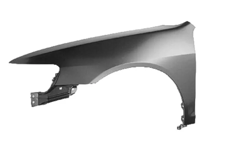
- In the case of half bumper type, we have a high possibility of reducing the scrap. By slightly increasing the blank size we can produce two fenders at the same time (scrap management). We can drastically reduce the wastage of material.
- Half bumper type fender allows us to use a lot of plastic on the bumper, which means we are reducing the certain proportion of weight from the fender. Hence, the lesser the weight higher the performance.
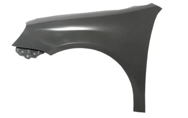
Mounting points in a fender:
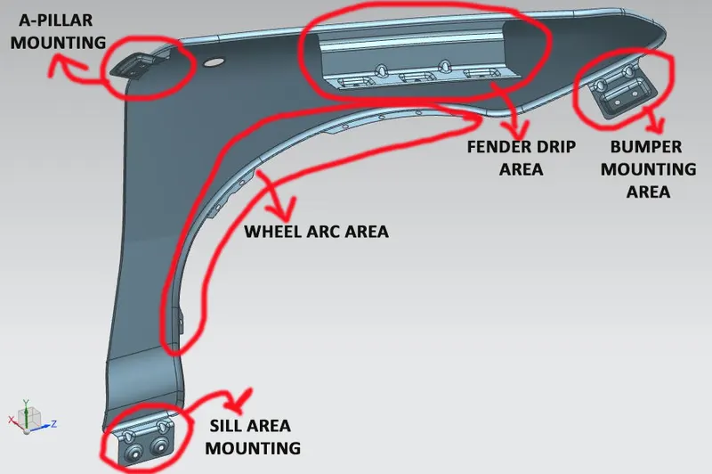
There are 5 mounting points in a fender
- Drip area
- Bumper
- A-pillar
- Sill
- Cowl
DRIP AREA:
- The drip area is a region that comes in contact with the engine compartment through deformable brackets with the help of fasteners.
- The drip area is one of the most important design considerations in the fender development process. There are certain design constraints (master section) that need to be followed by all the OEM's/automobile manufacturers.
- A gap of 200mm(conventionally) is maintained between the rear end of the fender and the drip area. This gap is sufficient enough to install the cowl plastic mounting and the wiper motor components.
- A gap of 150mm(conventionally) is provided between the front end of the fender and the drip area. The reason being, for the proper installation of the headlamps and their housing.
- The length of the drip area and the clearances provided depends on the length of the hood, unconventional size of the cowl, etc.
- The height of the fender should be 80mm(min) (child and 1700MAX).
- The height in the range of WAD1700MIN shall be 94mm (+14mm that corresponds to the amount of increase in inertial energy) to meet the adult impact requirements.
- A parting line shall be provided within a range of 47.5mm from SRL(side reference line), if there is no problem in terms of styling surface. If the value goes beyond 47.5mm then we must inform the styling team to do the required changes in the skin data.
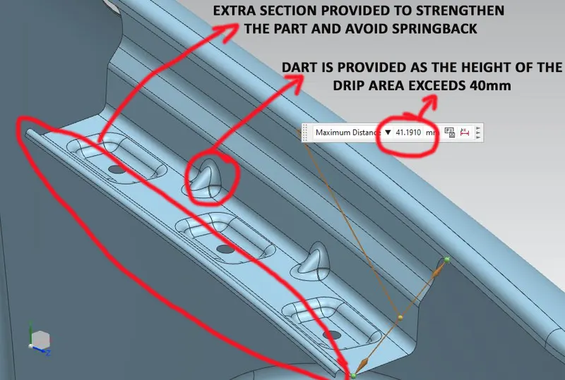
- If we are not sure about the height of the drip area then we provide ribs in order to strengthen the part and avoid the spring-back effect.
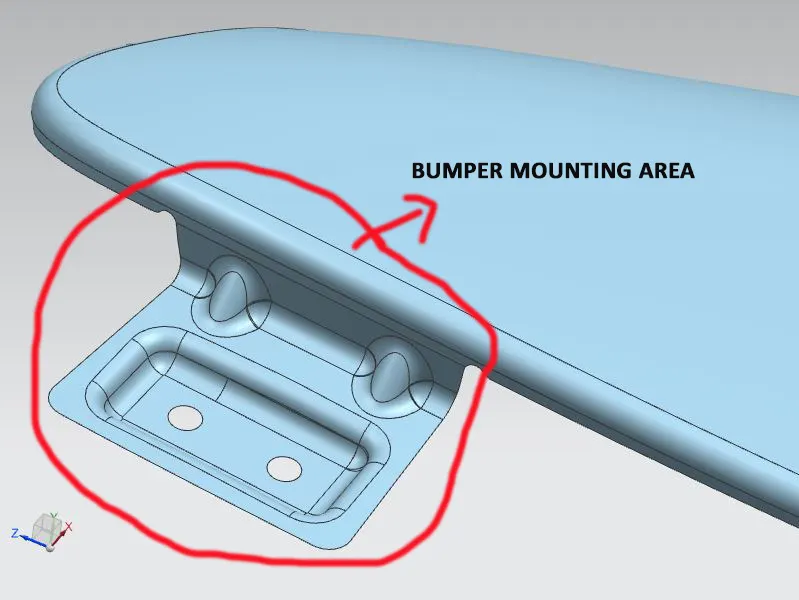
BUMPER MOUNTING AREA:
- A bumper is located on the front and rear of a vehicle. The purpose of a bumper is to absorb the impact of minor collisions.
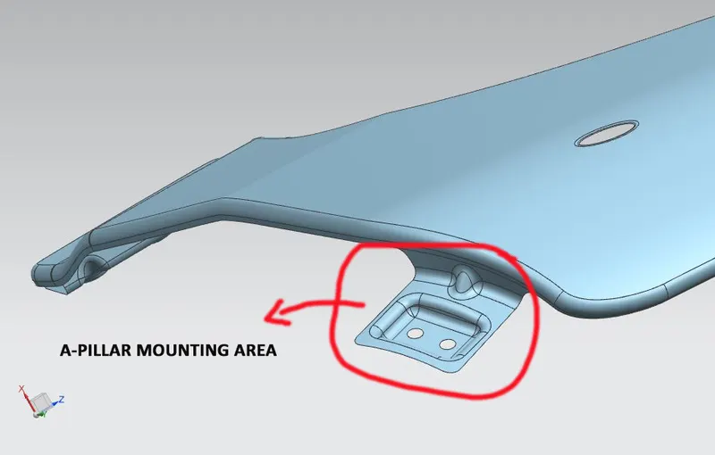
A-PILLAR MOUNTING AREA:
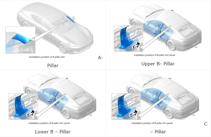
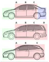
- There are three main types of pillars when referring to the design of a car - A, B, C.
- The pillar or the vertical bar which you see holding the windshield from sides, the right side A-pillar houses the Antenna in most of the cars.
B-PILLAR MOUNTING AREA:
- The B-pillar is present in between the rear & the front door.
C-PILLAR MOUNTING AREA:
- This is where your rear window ends but on the body & not on the door.
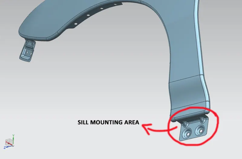
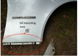
SILL MOUNTING AREA:
- The mounting area at the panel is directly below the bottom of the door supporting the base.
WHEEL ARC AREA:
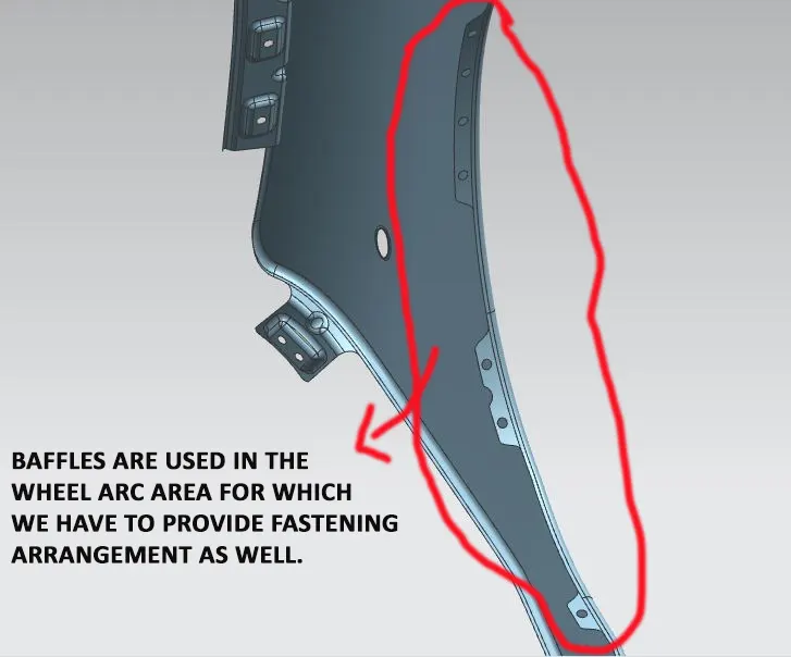
- It is the semi-circular region that forms wheel wells around the tires.
- There are certain wheel guard regulations that need to be followed. For every region, we have different regulations across the globe.
- Japan regulation standard: The value of clearance must be greater than 5mm at a line 30deg forward and 50deg rearward from the central vertical axis of the wheel.
- European regulation standard: The clearance must be greater than 10mm at a line 30deg forward and 50deg rearward, a line 150mm from the x-axis, midpoint between 50deg line and 150mm line.
- US regulation standard: The clearance must be greater than 5mm for every 10deg from -20deg to 180deg.
DESIGN METHODOLOGY:
Objective:
- Our objective is to design the automobile fender by considering the given skin data, design constraints, safety regulation, and manufacturability for the vehicle development process.
Design Data:
- Styling surface(skin data) of the fender provided by the styling team.
- The thickness of the fender = 0.75mm
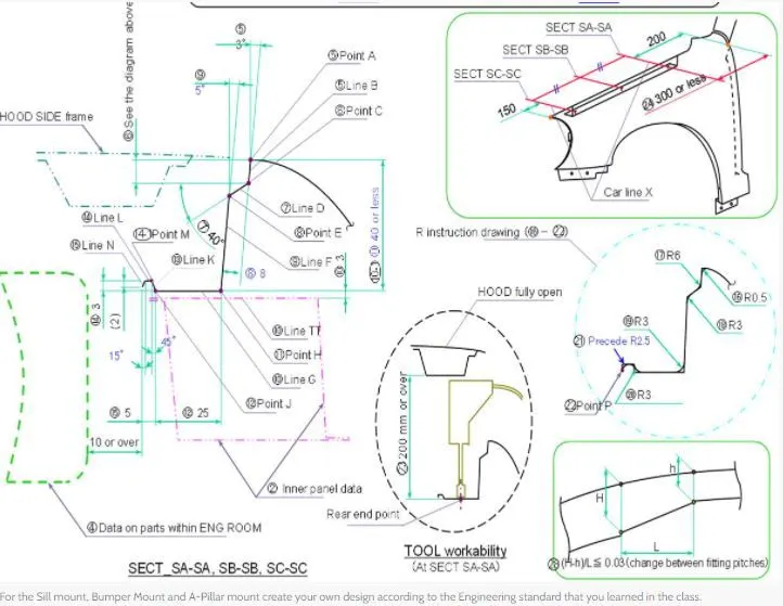
- Master section of the drip area that consists of dimensional values for fillet radii, width, flange clearance, etc.
Design process:
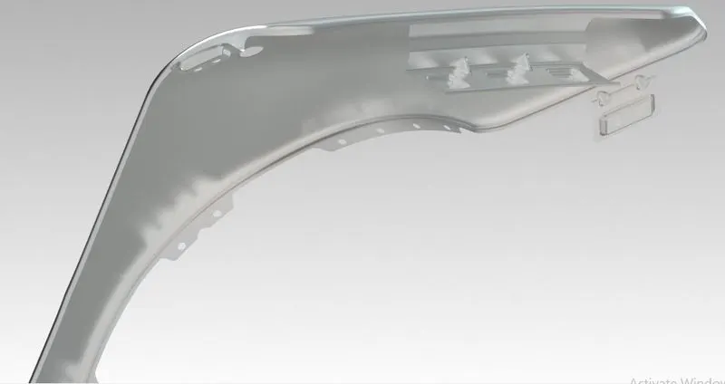
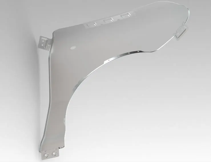
- First, we have developed the drip area from the given skin data and the master section. The most important consideration is the fender height which should be 40mm or less. But in our design, it is around 41-42mm. Hence, in order to strengthen the part, we have provided darts and extruded section. This also helps us to avoid spring-back.
- We have created two planes normal to the curve at 150mm and 200mm from the front end and the rear end of the fender. This provides us the area within which the drip area must lie. These values might change if we have unconventional design values for the cowl region or a larger hood length.
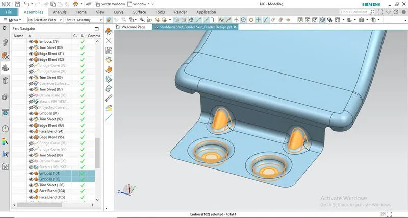
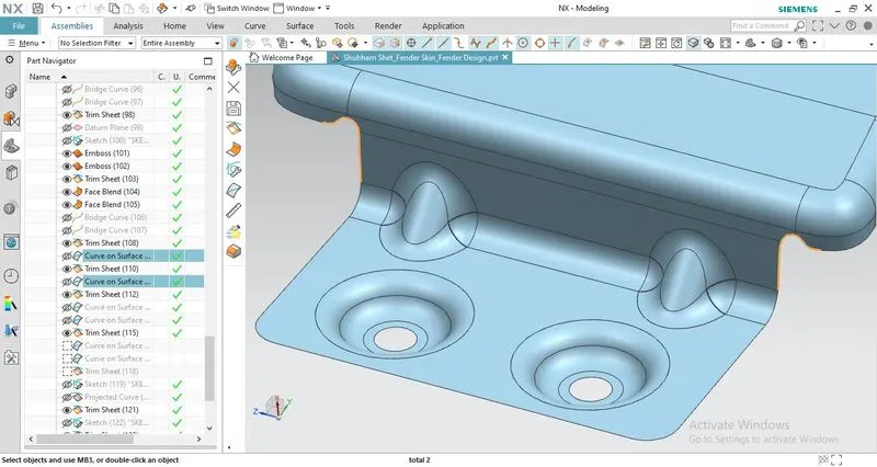
- For mounting points, we have created emboss with a mounting hole of dia 5mm. Fillet radii of 3mm are provided to all the edges and corners.
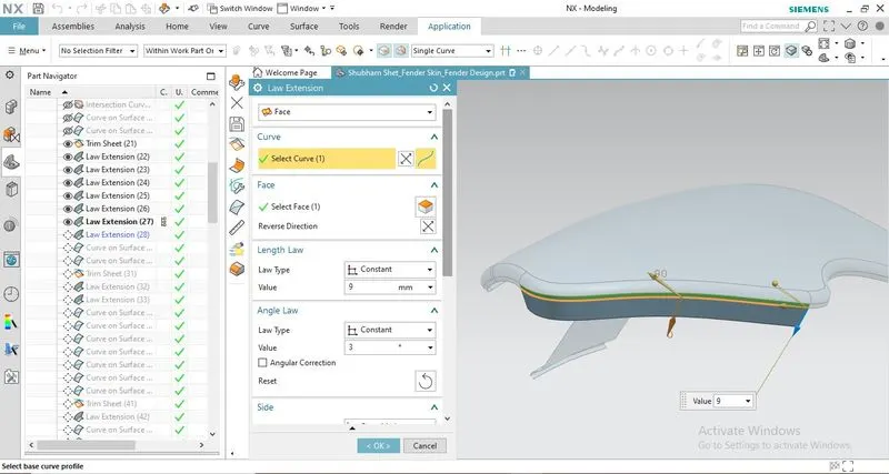
- As per the master section, the first flange of height 9mm at an angle of 3deg w.r.t vertical vector was created using the law extension command.
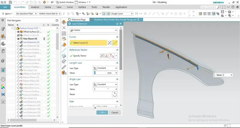
- Drip area region achieved by creating plane at 150mm and 200mm from front end and the rear end of the fender.
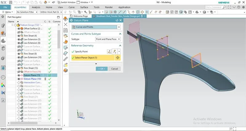
- A smooth transition is created between the two flanges using the curve on the surface command. By doing this we avoid unwanted sharp edges where the stress concentration is more.
- Another flange is created at an angle of 40deg w.r.t horizontal vector and a length of 8mm respectively.
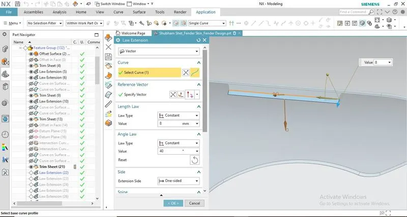
- Similarly, all the remaining flanges are created with the help of the given master section. Darts are also introduced in order to strengthen the part and avoid the spring-back effect. Then fillets are provided at all the edges, mounting embosses, etc.
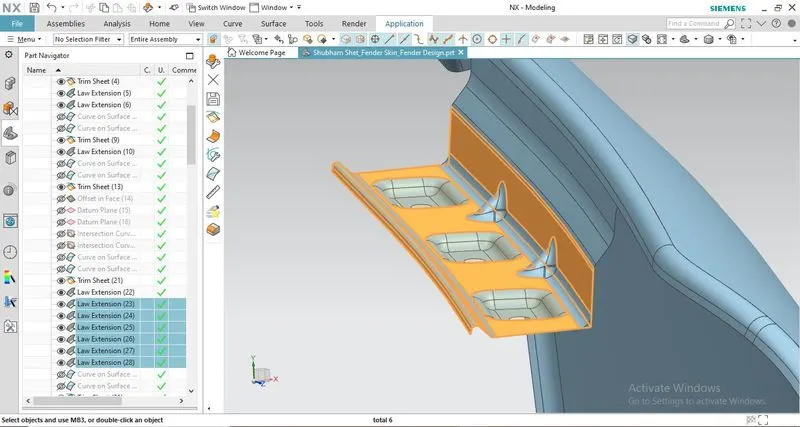
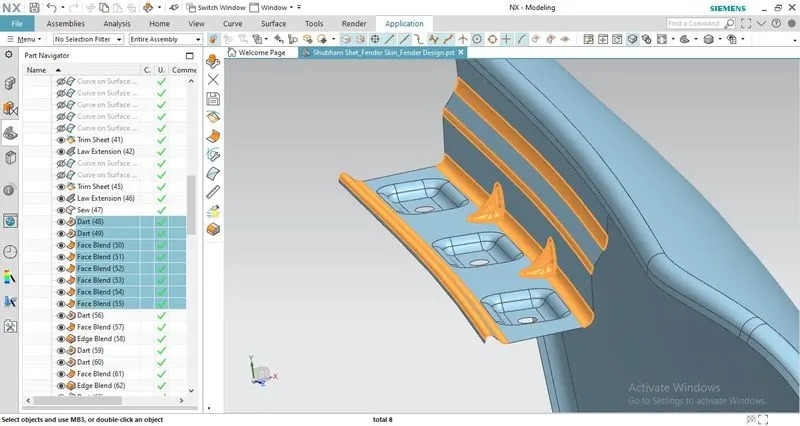
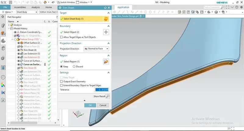
- We created another flange of length 9mm & at an angle of 3deg for the A-Pillar mounting. For a smooth transition between two flanges, we have created the desired curve and trimmed the unwanted flange material.
- Another flange of length 40mm and at an angle of 78deg & 90deg(linear angle law) was created. Mounting points were created using the emboss command and later darts & fillets were also introduced.
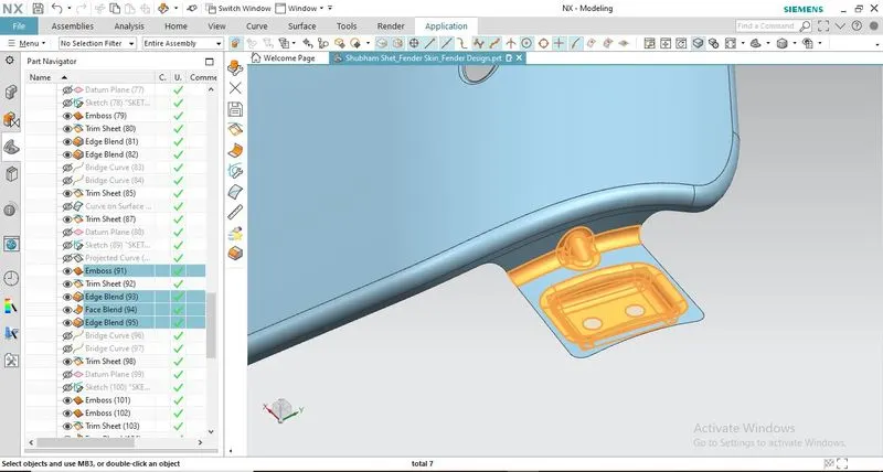
- Later, we created a flange for the bumper mounting area and then created a smooth transition between the two flanges. A flange of length 35mm and an angle of 90deg was created for the mounting area.
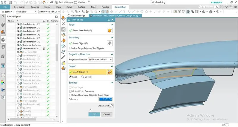
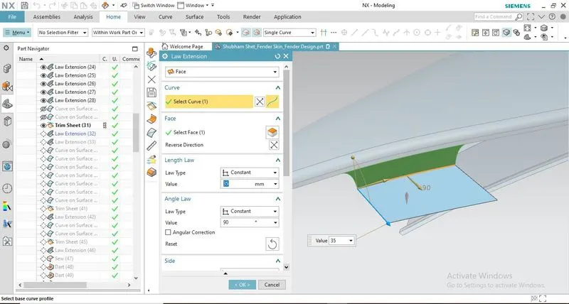
- Using emboss command bumper mounting area was created a hole of dia 5mm. Darts & fillets are provided on the edges.
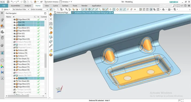
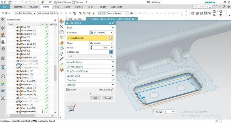
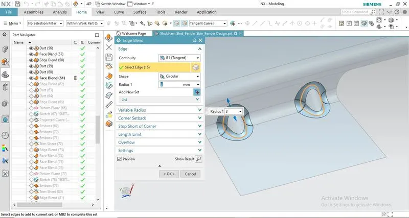
- Edge relief is provided at the corners to reduce the stress concentration.
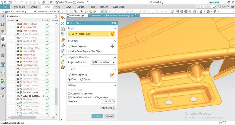
- The flange of length 10mm is created for the sill mounting area along with the edge relief provided at the corners.
- Another flange of length 30mm and at an angle of 90deg is created for the sill mounting emboss.
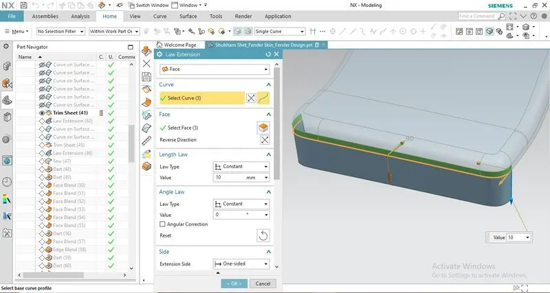
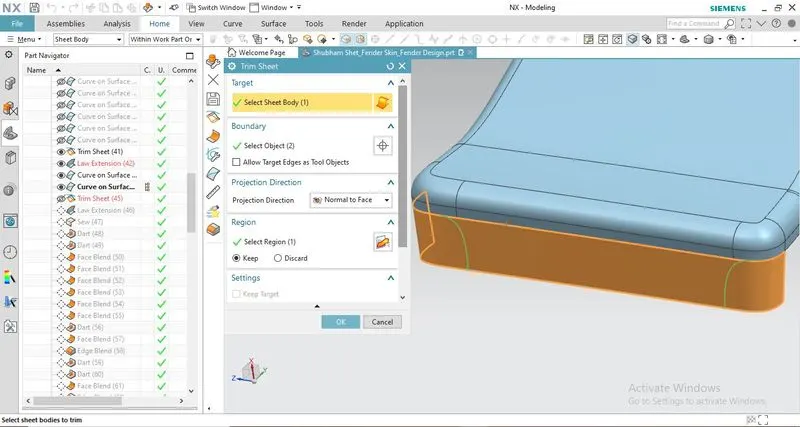
- Darts are provided at the bends for strengthening purposes and circular emboss is provided for the mounting purpose. Fillets are introduced at all the edges and relief is provided at the corners.
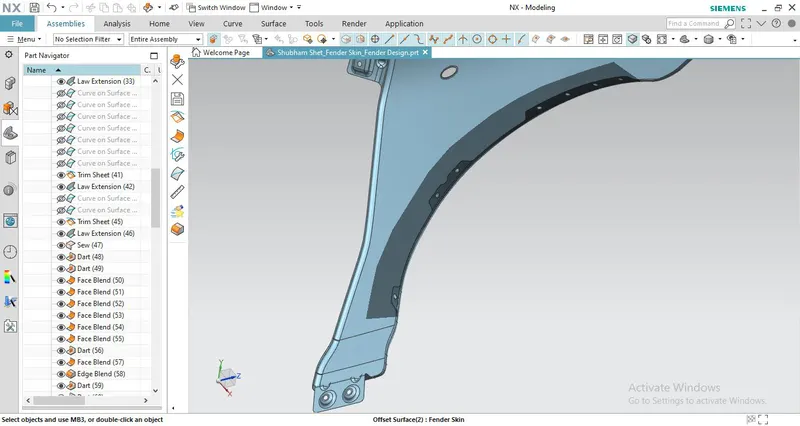
- A small flange is created in the wheel arc area for mounting the baffles that stop the debris from the road from damaging the components underlying the hood.
Manufacturability:
- Metal stamping manufacturing processes can quickly and cleanly create solid metal parts and forms. The process uses specialized dies that press sheets of metal into precisely the right form. Auto manufacturers benefit from using metal stamping for parts like fenders and hub caps because the dies can be used again to create consistently sized and shaped parts that meet tight specifications and tolerances.
- Metal stamping processes continue to develop and improve with new technology. Not only does the manufacturing process benefit from increased end-to-end automation, but the stamping machinery is also becoming more advanced.
- One popular advancement is the use of electromagnetic tools. These devices can better interact with sheet metal by using electromagnetic forces to precise position the sheet metal. Electromagnetically assisted tools can both make more intricate, complex forms and reduce material waste by narrowing the margin between stamps.
-
There are three popular types of metal stamping presses used for automotive and other industrial parts. They include:
- Mechanical presses, which have a mechanical flywheel powered by a motor.
- Hydraulic pressures, which have pressurized fluids that control the pressure and application of force on a workpiece.
- Mechanical servo presses, which use only motors and no mechanical flywheels.
All three press types can work with automated systems, such as automatic feeders, to increase efficiency and production speed. Automatic feeders send coiled or blank sheet metal through the presses to create a fast run.
- Some key benefits of metal stamping include:
- Cost-Effectiveness: Once the dies have been made, manufacturers can create high-volume runs of automotive parts at a low cost. Metal stamping techniques can handle a variety of metals, which allows companies a large degree of flexibility without additional costs. The metal stamping dies themselves are also cost-effective to create and keep in good working condition. The finishing steps of producing the parts, like plating, are also cost-effective.
- Material Efficiency: Metal stamping processes use sheet metal to create parts. Sheet metal is efficient and doesn’t add wasteful heft or thickness to the part. Sheet metal can be used for an array of parts, including structural elements, the chassis, and mechanical components in the engine or transmission systems.
- Automation: Metal stamping processes can be handled entirely by machinery. Not only does this reduce the risk of human error or inconsistency, but it also lowers labor costs and keeps employees safe.
- Metal stamping presses and dies can work with many different metals to create diverse parts. Some of the most commonly used metals in stamped automotive parts include aluminum, copper, and steel. Each metal has unique attributes that make it ideal for certain applications.
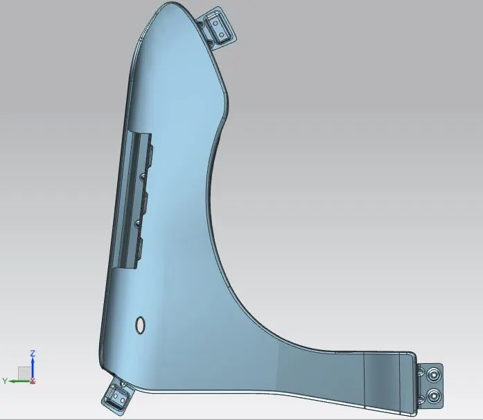
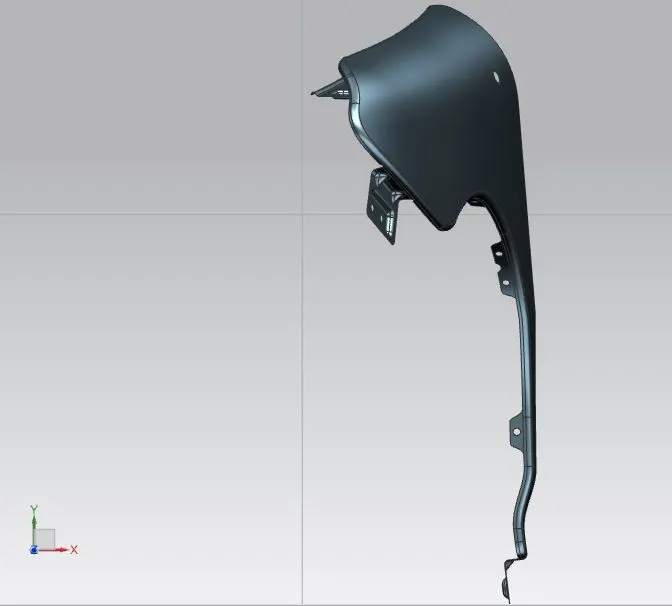
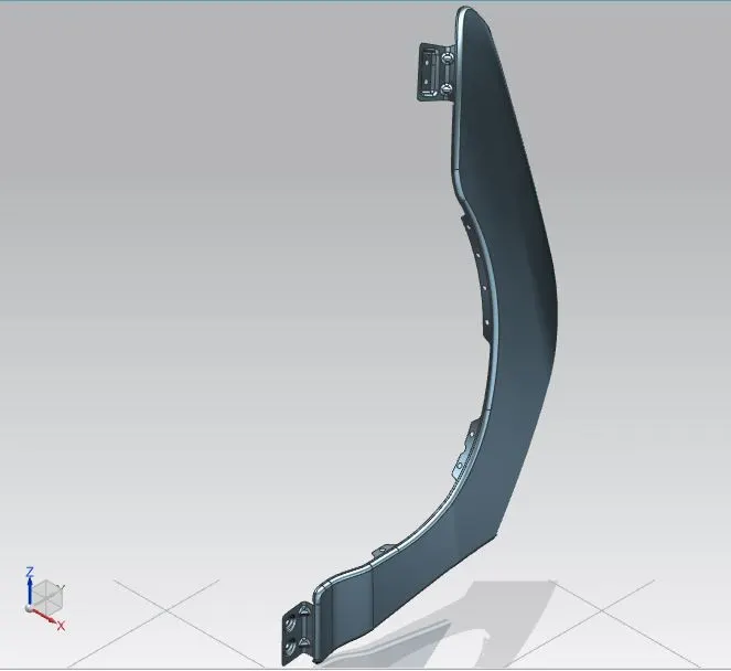
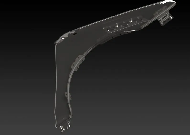
Drawing Views:
Front View
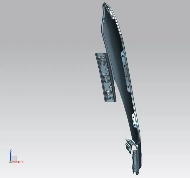
Side View
Top View
Isometric View
Rendered Image
Conclusion:
- Successfully designed the automobile fender by following all the design considerations such as drip area, wheel arc area, pedestrian safety, bumper mounting area, sill mounting area, A-pillar mounting area, manufacturability, etc.
- Examined the geometry for any sort of geometric discontinuity, irregularities in blends, etc.
- Got to learn and implement various modeling, surface, curve tools in NX CAD and CATIA to design the hood.