Fender Design Challenge
DESIGN OF FENDER
Fender is an English US term for the part of an automobile (vehicle body) that frames on wheel (the fender outside). The primary purpose of the fender is to prevent sand, mud, rocks, liquids and other road spray from being thrown into the air by rotating the tyre.
When the wheel is moving, tyres pick up stones and other hurl them in all directions. Fenders are basically present to prevent any injuries to pedestrians and contain the motion of these particles.
Most passenger vehicles have four fenders, one over each wheel for vehicle with a narrow car body that exposes the tyre. The fender is an exposed curve over the top of the tyre. For wide body vehicles that covers the tire, the Fender forms the wheel well surrounding the tyre and not directly visible from above the car body.
Wheel wells tend to be much larger than the diameter of the tire. Because they do not move with the tire suspension and consequently must be large enough to allow the full range of tire motion on the suspension without touching the interior of the wheel. More elaborate designs include fender parts for enclosing the outside edge of the wheel well and stylized pontoon fenders for exposed fenders.
Fenders are mainly two types. They are,
- Full bumper type
- Half bumper type
Full bumper types are not used in nowadays. Since they require more blank size as compared in half bumper type. As a result, in large scrap to be produced. In half bumper type, the slight increase in band side which accommodate two fenders in one fender which result in reduction of scrap. In half bumper type, plastic parts are generally used at front end which also reduced in weight.
OBJECTIVE:
In this project mounting section is designed for the front fender. Fender has especially five mounting regions. They are,
- Body
- A pillar
- Sill
- Cowl
- Drip area.
DESIGN CRITERIA OF FENDER:
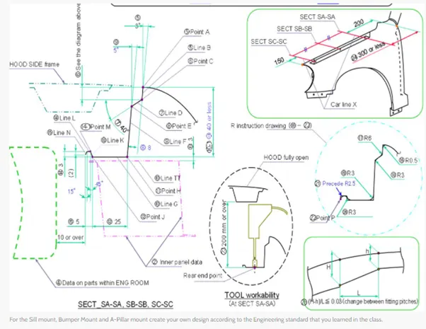
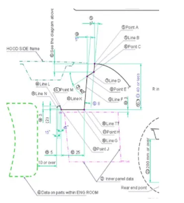
By using this master sketch and given fender skin data, a design is developed for the fender with 5 mounting regions. Each mounting bolt is designed as per the tool work ability regions.
A-Piller mount:
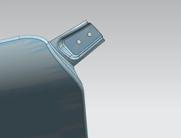
Body mount:
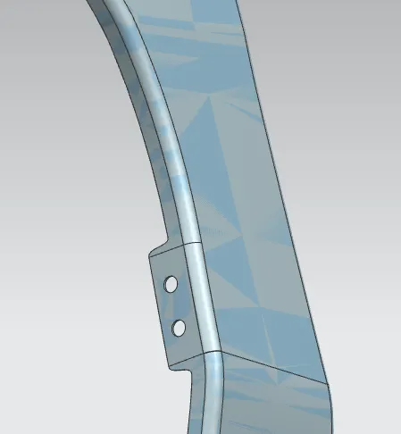
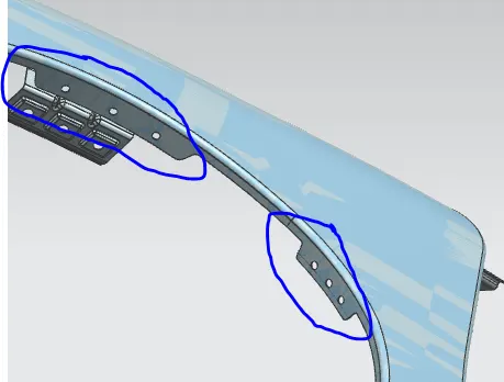
Sill mount:
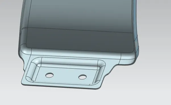
Cowl or baffle mount:
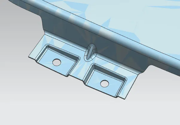
Drip area mount:
drip area is the point of contact with the engine compartment. The drip area of the fender as per the master sketch is consider as 200mm from the backside to fix the wiper motors and 150mm from the front side to fix the head light. The initial opening angle is given for 3° and depth for about 9mm. 50mm or lesser distance is given for the tooling operations, if it is more than 60mm it results in spring back effect. And the structure of drip area is provided with dart to strengthen the component.
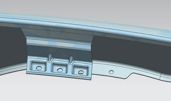
IMAGES OF DESIGNED FENDER:
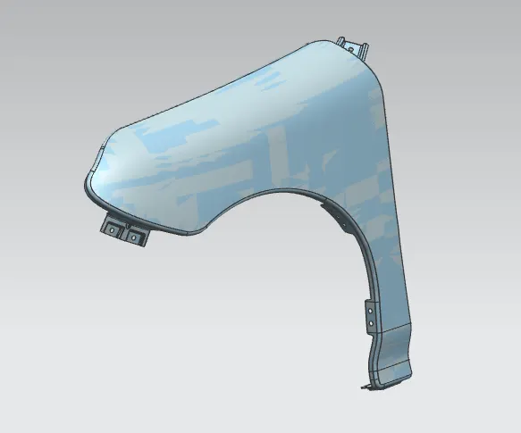
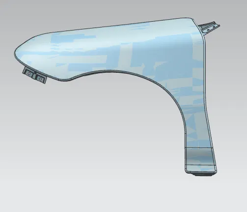
CONCLUSION:
The fender is designed as per the master sketch. the major criteria which applied on this design is to stiffen the component and for providing comfortable tooling operations as per the master sketch.