Fender Design Challenge
FENDER:
the fender is US ENGLISH terms for the part of an automotive (vehicle body ) that frames a wheel well.
its primary purpose is to prevent sand, mud, rocks liquids. and other roads spray from being thrown into the air by rotating the tire.
when the vehicle moving, tires pick up stones and others and hurl them in all directions, fenders are basically present to prevent any injuries to pedestrians and contain the motion of these particles.
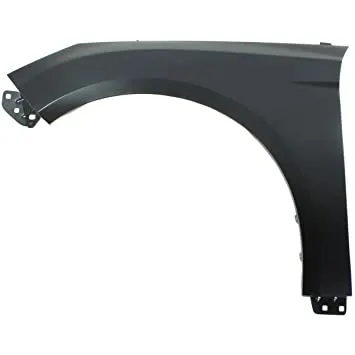
REQUIRMENTS OF THE FENDER.
- Design requirements of the fender and its components.
- functional requirements
- important regulation
- drip area
- wheel arch
- baffle and ORVM MOUNT AREA
- FRONTAL CRASH REGULATION and requirements
- gap and flushness requirements
-
there are two types of fender
1, full bumper type
2, half bumper type
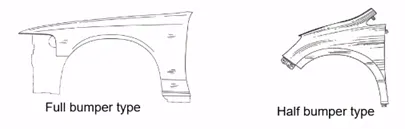
-
from the full dumper, the material gets removed and gets weight reduction that is nothing but half bumper.
Mounting
- there are 5 types of mounting points in a fender.
- they are
- body
- A-pillar
- sill
- cowl
- drip.
Below the figure is used as a master section to create a drip area The rest of the mounting points are created as per the design requirements.
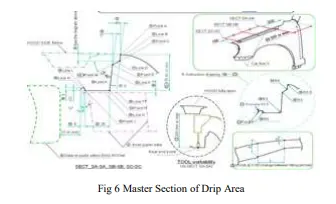
Drip Area
- It is the critical mounting area located inside the engine component. Designed according to the master section, an optimal opening angle is maintained to make it look well assembled from the outside.
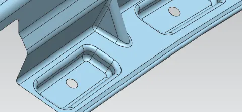
- Minimum clearance from headlamp and cowl part is maintained. The vertical distance of the drip mounting is maintained at less than 40mm to avoid the spring-back effect. The drip area is mounted to the engine compartment by weld nuts.
- A-pillar mounting :
- minimum clearance from the tire distance required.
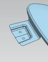
OPERATION PERFORMED IN NX CAD.
- fender skin is proved.
- we have to design the A PILLAR MOUNTING AND DRIPS.
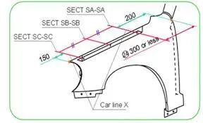
-
by using the datum plane set get the required length.
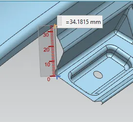
-
drip length as to be below 40mm.
-
50mm are 60 mm then spring action is formed.
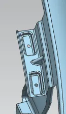
- after providing the respective lengths and angles.
- by using this master section create the drip area.
- give the required length.
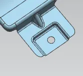
- A pillar mounting by using law extension at the required angle.
-
if required drat can be placed at the required place.
drat, place according to your requirement.
EXTEND the boundaries at the length of 5mm.
emboss command also used length 5 mm and angle 10 mm.
holes are made by using the trim.
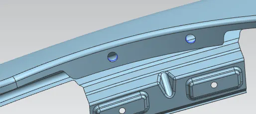
- if create the drip are a pillar, it goes near the tire and may cause any issues.
- rubber and push clips are placed in that hole.
- to get the required shape command used cure on surface and bridge curve command.
-
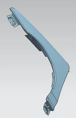
final output:
-
Fender finger: