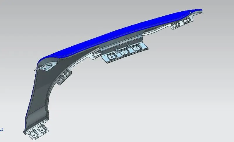
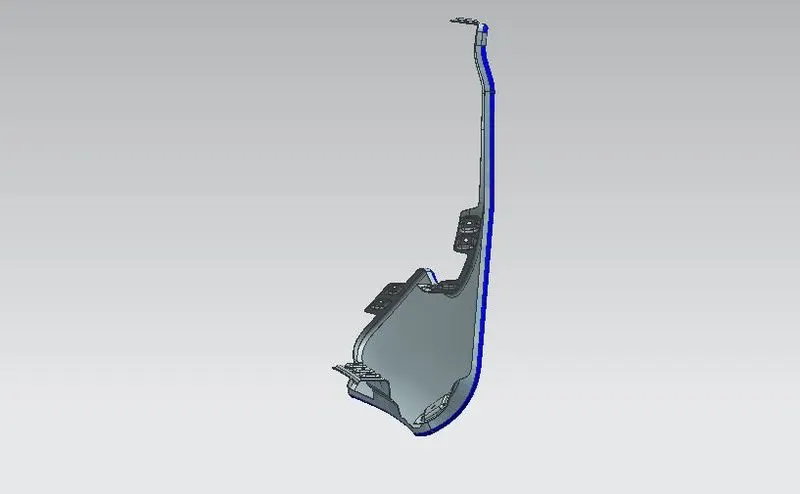
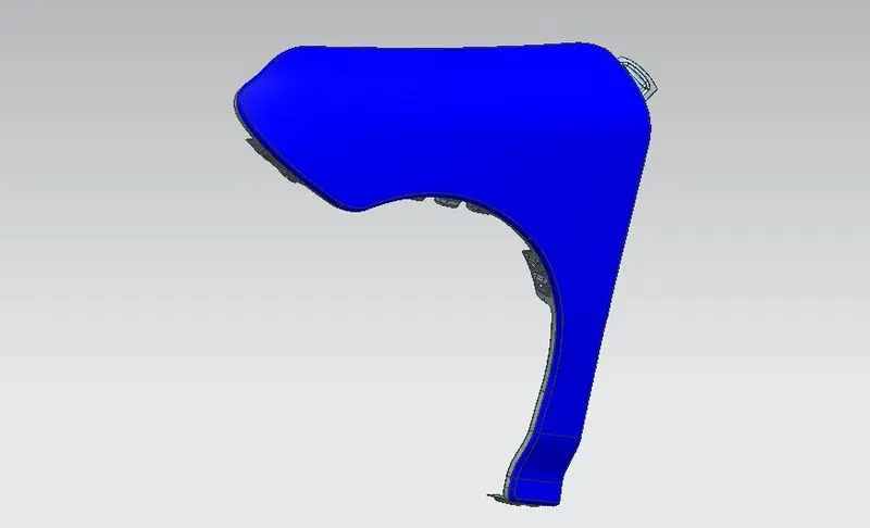
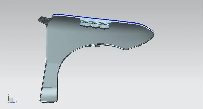
Fender Design Challenge
DESIGN OF FRONT FENDER
Aim :
To create design of fender by using of NX CAD from master section
Fender :
Fender is the American english term for the part of an automobile, motorcycle or other vehicle body that frames a wheel well (the fender underside). Its primary purpose is to prevent sand, mud, rocks, liquids, and other road spray from being thrown into the air by the rotating tire. Fenders are typically rigid and can be damaged by contact with the road surface.
Types of Fender :
1. Full bumper type
2. Half bumber type
Manufacturing process involved:
1.Blanking
2.Bending
3.piercing
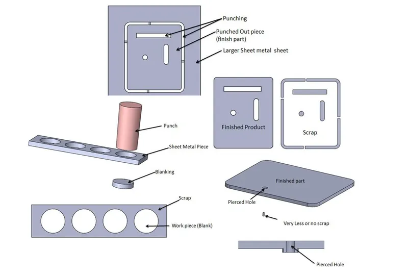
Blanking and piercing
Punching :
Punching is a forming process that uses a punch press to force a tool, called a punch, through the workpiece to create a hole via shearing. Punching is applicable to a wide variety of materials that come in sheet form, including sheet metal, ,paper, vulcanized fiber and some forms of plastic sheet. The punch often passes through the work into a die. A scrap slug from the hole is deposited into the die in the process. Depending on the material being punched this slug may be recycled and reused or discarded.
Punching is often the cheapest method for creating holes in sheet materials in medium to high production volumes. When a specially shaped punch is used to create multiple usable parts from a sheet of material the process is known as blanking. In metal forging applications the work is often punched while hot, and this is called hot punching. Slugging is the operation of punching in which the punch is stopped as soon as the metal fracture is complete and metal is not removed but held in hole.
Bending :
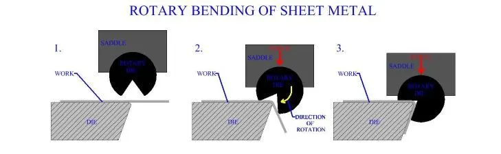
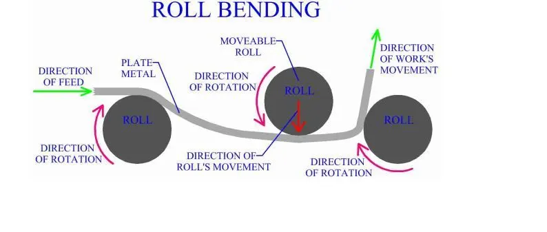
Bending is a manufacturing process that produces a V-shape, U-shape, or channel shape along a straight axis in ductile materials, most commonly sheet metal. Commonly used equipment include box and pan brakes, brake presses, and other specialized machine press. Typical products that are made like this are boxes such as electrical enclousers and rectangular ductwork.
In press brake forming, a work piece is positioned over the die block and the die block presses the sheet to form a shape. Usually bending has to overcome both tensile stress and compressive stress. When bending is done, the residual stresses cause the material to spring back towards its original position, so the sheet must be over-bent to achieve the proper bend angle.
Design Approach
Master section:
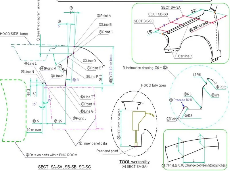
Mounting point of fender :
1. Drip
2. Bumper
3. A pillar
4. Cowl
5. Sill
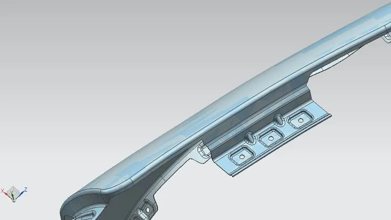
Drip Area :
It is used to connect the fender to the engine compartment
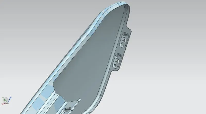
Bumper :
As the name suggests, a car bumper is used to absorb impact in the event of a collision, resulting in lesser costs in repair and damages. There are two locations in a car where you can find a bumper, namely the front end and the rear end. Both the front and rear bumpers are used to protect the car from unwanted damage.
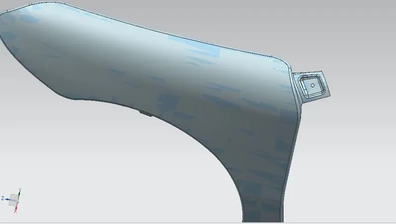
A pillar :
This pillar provides structural support for the vehicle's roof panel and is designed for latching the front door and mounting the hinges for the rear doors.
Manufacturers provide the A-pillars on both sides of the vehicle. The A-pillar is made of strong steel alloys. This is to make it withstand a crash and meet safety standards.
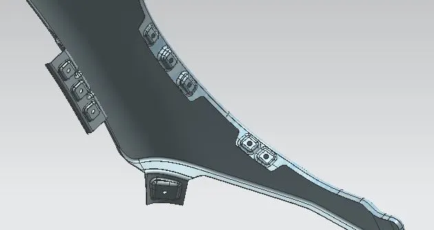
Cowl and Baffle :
The “cowl” is located in the space between the hood and windshield. This is the space where your vehicle’s windshield wipers are located.
Baffle is the rubber part that is attached to the fender so as to reduce the nice and vibration level
Sill :
Sills are usually the flat part of the bottom of a frame for an object – think windowsill – a strong and settled foundation from which the object can be built. The same goes for the early cars. From a solid sill between the wheels the body of the vehicle can then be built
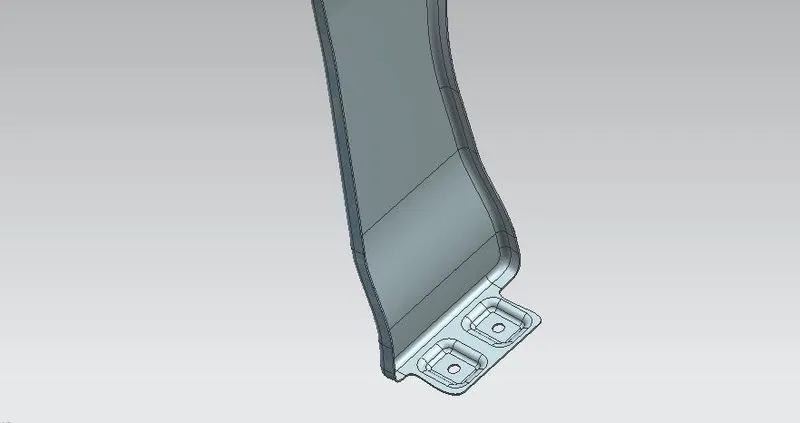
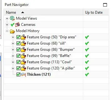
Different views of Fender