Fender Design
FENDER DESIGN
Objective:
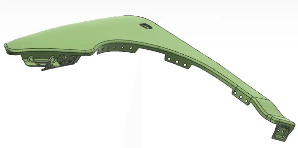
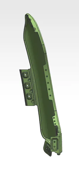
The objective of this project is to design the Body-in-White (BIW) front fender using the provided skin surface and master section. The design process includes the creation of key mounting features such as the Drip Area, A-Pillar, Sill, Bumper, and Baffle (Splash) mounts, utilizing Siemens NX CAD software.
What is a Fender?
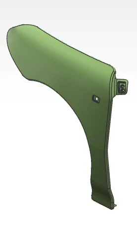
A fender is an essential exterior body panel located above the vehicle's wheels. Its primary function is to prevent road debris such as mud, stones, and water from being thrown into the air by the rotating tires. This not only protects the vehicle’s underbody and suspension components but also safeguards nearby vehicles and pedestrians. Fenders also contribute to the aerodynamics, safety, and overall aesthetics of the vehicle. The term “fender” stems from its role in "fending off" debris from the wheel area during motion.
Types of Fenders:
Fenders are generally classified into two main types based on their design and manufacturing approach:
Full Bumper Type Fender
l This type extends over the entire bumper area.
l Not commonly used today due to the requirement for larger sheet metal blanks, which increases material cost and results in significant scrap.
l Less efficient in terms of manufacturing and material utilization.
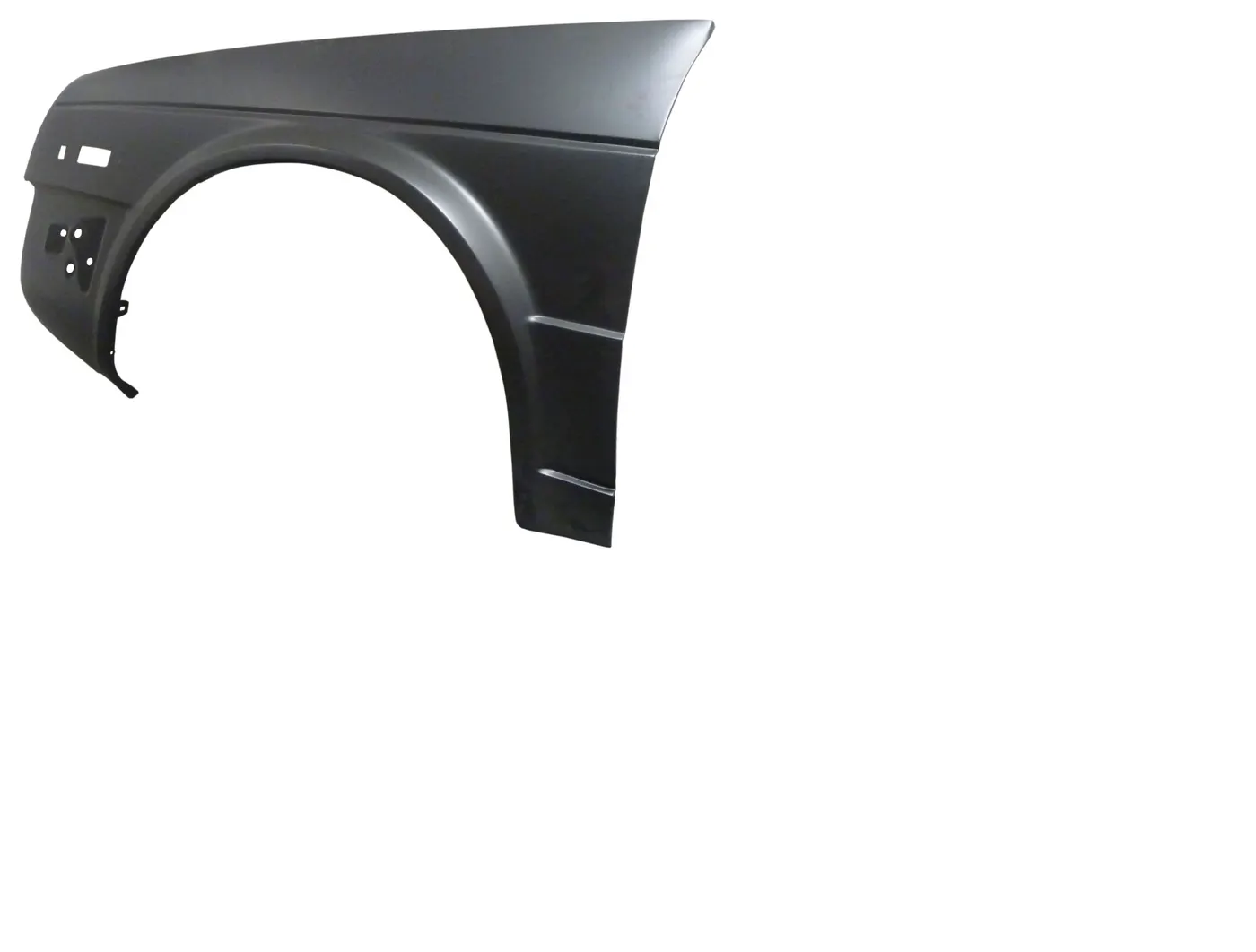
Half Bumper Type Fender
l Covers only a portion of the bumper area.
l Widely used in current and future vehicle designs due to smaller blank size requirements and reduced material wastage.
l More cost-effective and efficient for mass production.

Uses of Car Fenders:
l Protect the car's body and engine from mud, water, and corrosive elements.
l Enhance passenger safety by absorbing impact during collisions.
l Improve aerodynamics by reducing wind resistance.
l Add to the vehicle’s appearance, with options for universal or custom-designed fender flares.
Key Areas to Consider in Fender Design:
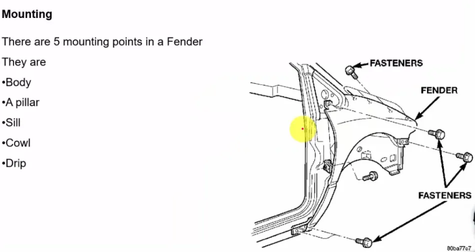
l Drip Area – For fastening the fender to the engine compartment.
l Bumper Mounting Area – Connects the fender to the front bumper.
l Sill Mounting Area – Provides structural support and attachment to the sill.
l A-Pillar Mounting Area – Ensures proper alignment with the A-pillar and door.
Indicator Mount – Space for integrating side turn indicators or signal lamps.
Drip Area:
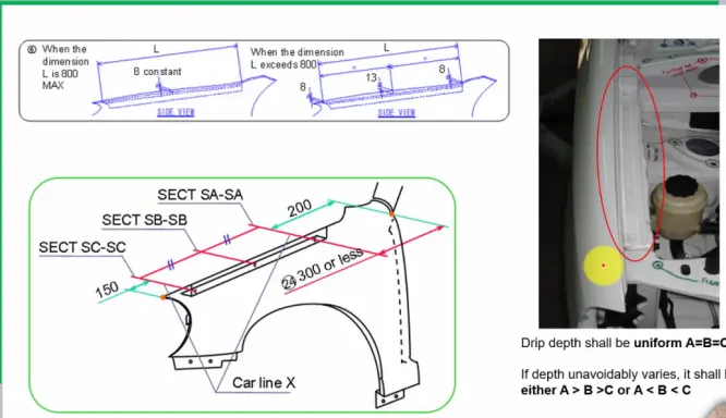
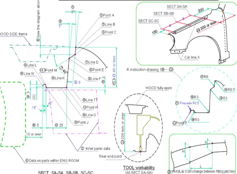
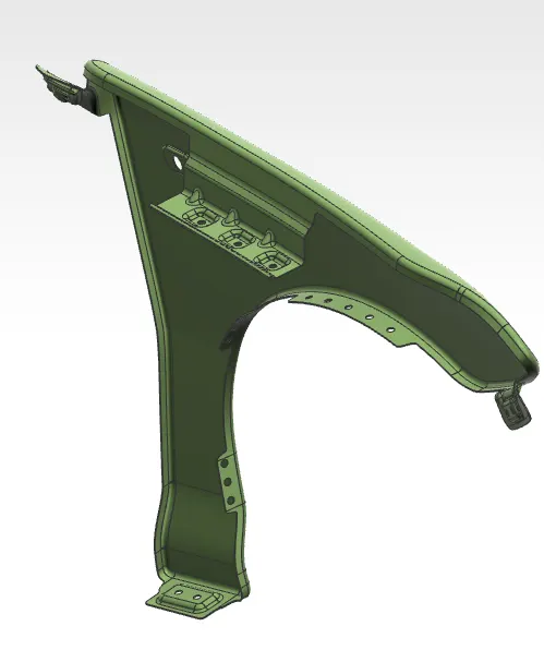
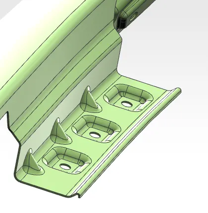
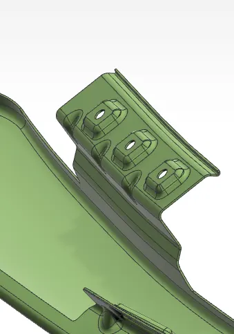
The drip area is a critical mounting zone where the fender attaches to the engine compartment using weld nuts. To ensure proper fit and avoid interference:
l Maintain 150 mm clearance at the front and ≤300 mm at the rear.
l Keep the drip height under 40 mm to reduce spring back during manufacturing.
l Ensure 10 mm minimum gap from nearby engine components.
l A rigidity bead is added at the end to enhance structural strength.
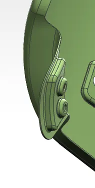
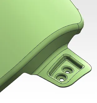
A-Pillar Mounting Area:
The A-pillar area is where the fender mounts near the windshield, typically hidden behind the side mirrors.
l Mounting is done using fasteners, with embosses and holes provided for strength and assembly.
l A sweep cut is created along the split edge with dimensions of 42 mm length at 5°, followed by another sweep of 6 mm at 45°.
l The surface is offset by 5 mm, with a 5 mm hole trimmed for mounting.
l Edge and surface fillets of 3 and 5 mm are applied for smooth finishing.
Sill Mounting Area:
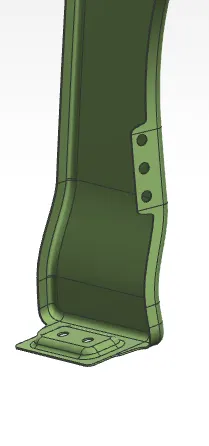
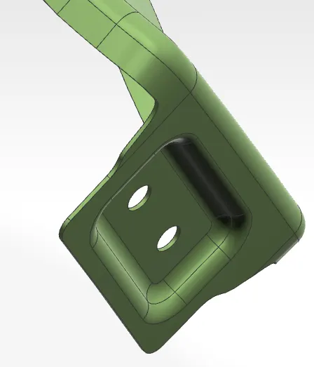
Located at the bottom of the fender, this area connects to the door region.
l Embosses and fastener holes are added for secure mounting.
l A 42 mm Law extension at 90° is made from the edge.
l The surface is offset by 5 mm, and a 5 mm hole is trimmed.
l 3 mm fillets are applied for smooth edges.
Baffle (Wheel Arch) Splash Area:
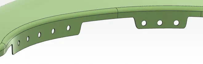
This area is designed to mount baffles that protect the wheel arch.
l 5 mm holes are created on the Trim sheet within the wheel arch region for fastener placement.
l Proper hole positioning ensures easy assembly and prevents interference with tire movement.
Bumper Mounting Area:
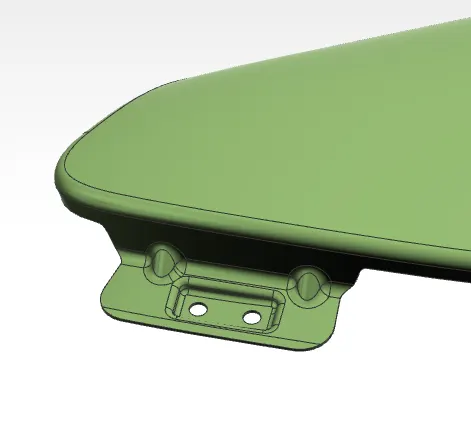
This area connects the fender to the bumper and must be structurally strong to absorb collision forces.
l A 20 mm Law extension at 90° is made from the edge, followed by a 3 mm Law extension at 90° on the split face.
l The surface is offset by 5 mm, and a 5 mm hole is trimmed for fastening.
l 5 mm edge fillets are applied for smooth transitions.
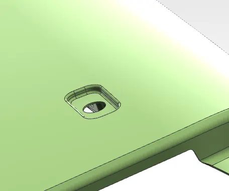
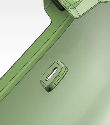
Indicator Mounting Area:
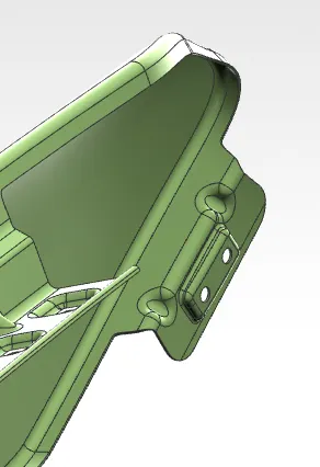
l Create a sketch and emboss the surface in 3mm.
l 5mm hole will done by using trim sheet.
l Edge fillet given in 2mm.
Common Commands for Designing Mountings:
1. Offset Surface – Offsets a surface by a specific distance from the original.
2. Trim Sheet – Removes unwanted portions of a surface using a curve.
3. Sew – Joins multiple surfaces into a single continuous surface.
4. Projected Curve – Projects 2D sketches onto curved or flat surfaces.
5. Edge Blend – Applies fillets to the edges where two surfaces meet.
6. Emboss – Extrudes a curve with draft to create features like mounting bosses.
7. Thicken – Converts a surface into a solid by adding thickness.
8. Datum Plane – Creates a reference plane based on geometry or origin.
9. Extend Sheet – Extends surface boundaries to the required distance.
10. Offset Curve in Face – Offsets curves within a surface boundary.
11. Offset (Sketch) – Offsets lines, arcs, or profiles in the sketch environment.
12. Law Extension – Extends a surface based on a law or guide curve for smooth transitions.
13. Through Curve Mesh – Creates complex surfaces by blending multiple section and guide curves.
14. Dart – Adds a dart feature (a narrow indentation or fold) to increase local stiffness in the sheet metal or plastic part.
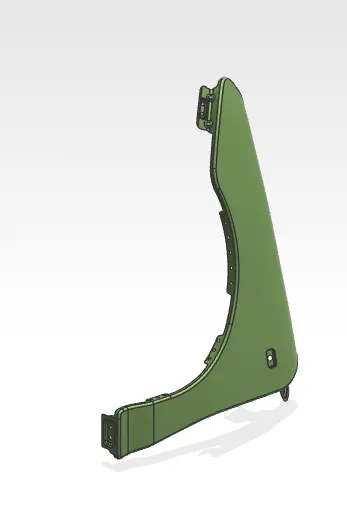
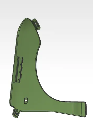
All the views:
Conclusion:
Thus, all the fender mounting areas were successfully designed using the provided skin surface and master section, while adhering to standard design guidelines and best practices.