Fender Design
1. Aim
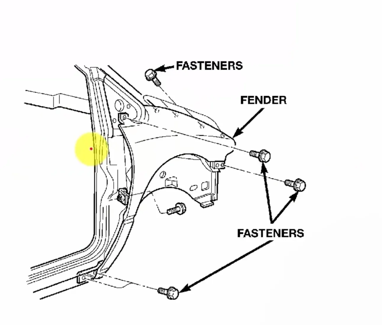
The objective of this project is to design the mounting points of the front fender at the following Mounting Areas:
a. Bumper Mounting
b. Drip Mounting
c. A-Pillar Mounting
d. Sill Mounting
e. Baffle Mounting
2. Introduction
a. Overview of a Fender
A fender is an essential component of an automobile, designed to frame the wheel and prevent debris such as sand, mud, and small rocks from being thrown into the air by rotating tires. This helps protect pedestrians, nearby vehicles, and engine components from damage.
Fenders also play a crucial role in improving the aerodynamics of a vehicle, contributing to fuel efficiency and stability at high speeds.

b. Types of Fenders
There are two primary types of fenders used in automobiles:
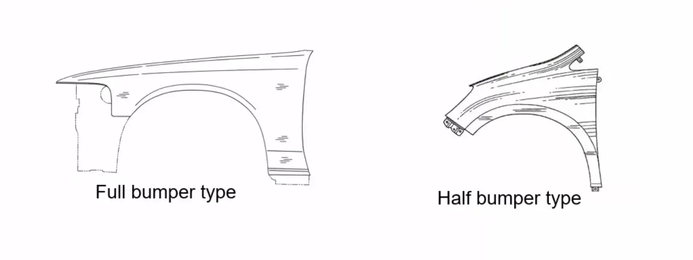
1. Full Bumper Type Fender
• Covers the entire front wheel area, extending from the headlamp to the A-pillar.
• Results in higher material consumption and increased manufacturing costs.
• Commonly used in older vehicles.
2. Half Bumper Type Fender
• Covers only up to the headlamp, reducing the sheet metal blank required.
• Allows the production of two half-bumper fenders from a single blank, leading to cost savings and minimal scrap waste.
• More common in modern car designs due to its economic and environmental benefits.
3. Design Features of the Fender
a. Bumper Mounting
The bumper mounting area provides attachment points for securing the plastic bumper to the fender using fasteners. This ensures a seamless fit between the bumper and fender, maintaining both structural integrity and aesthetics.
b. Drip Mounting
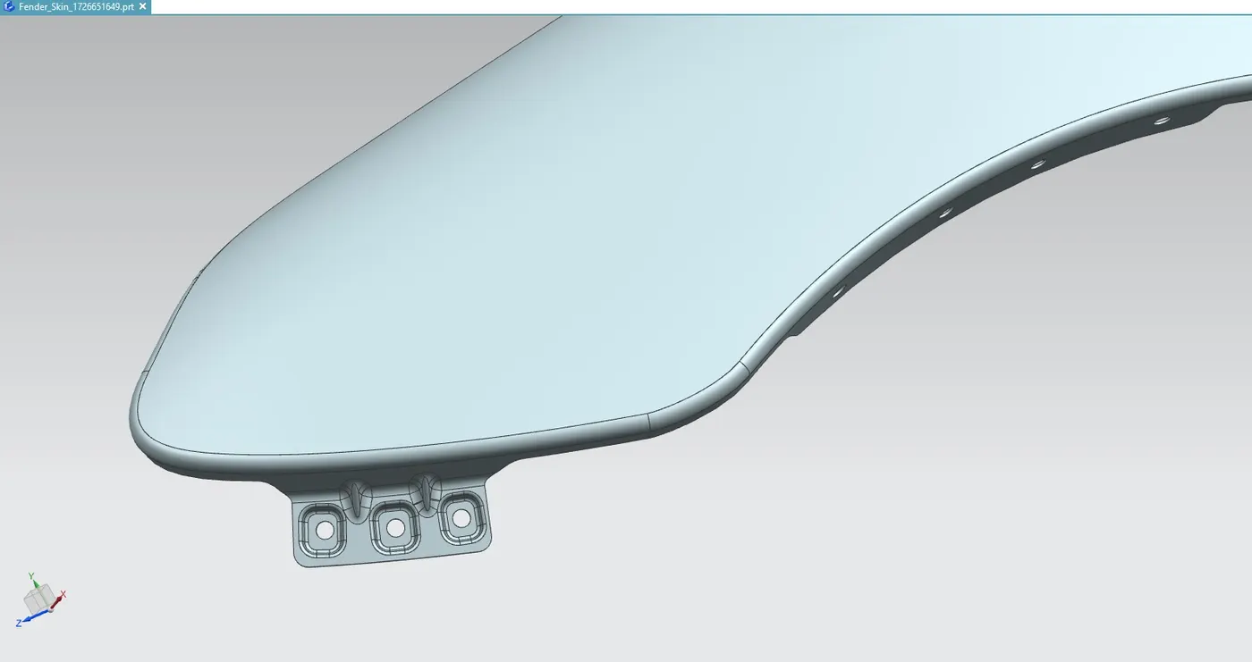
The drip mounting area is one of the most critical sections of the fender. It connects the fender to the engine compartment, which requires strict design constraints to ensure proper fitment.
Key Design Considerations:
• Maintain a clearance of 200-300mm for the cowl top to accommodate the wiper motor assembly.
• Ensure a minimum clearance of 150mm at the front for headlamp placement.
• The mounting height should be less than 40mm to reduce the spring-back effect during manufacturing and minimize NVH (Noise, Vibration, and Harshness) issues.
• Mounting holes of 5mm diameter with locator pin holes are designed for accurate positioning.
• Strengthening features such as ribs and embosses are added for structural support.
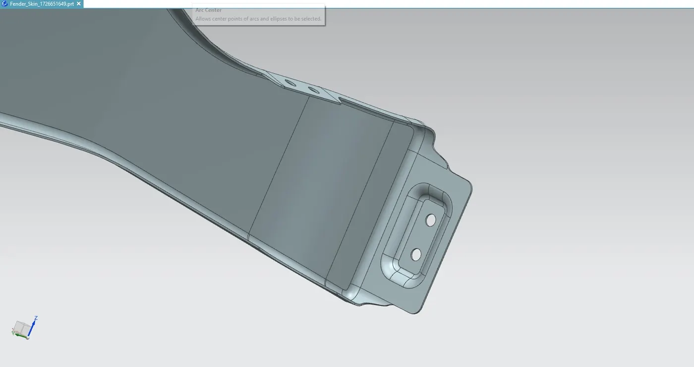
c. Sill Mounting
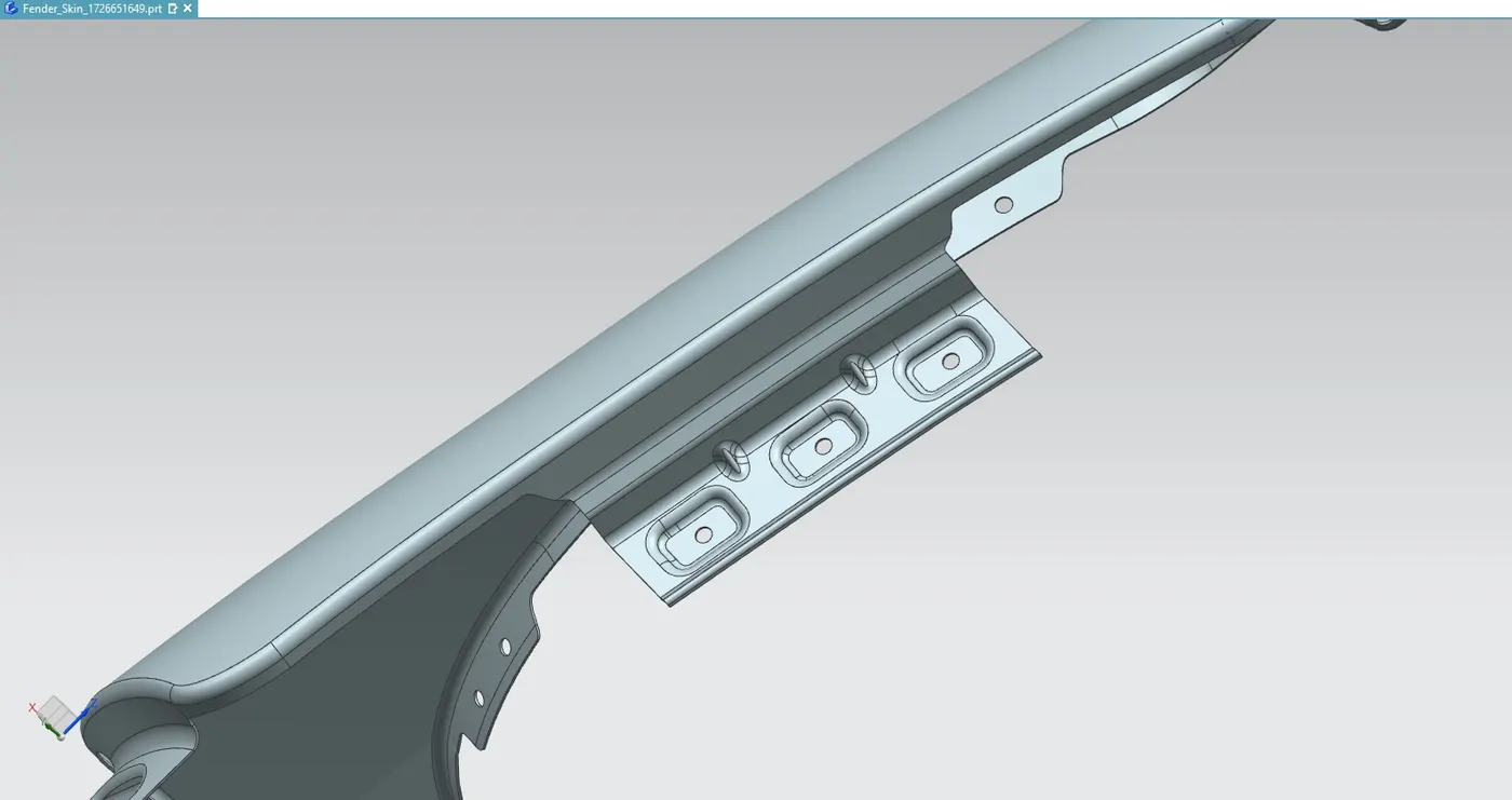
The sill is the structural component located below the car door, supporting the vehicle's floor panel. The bottom end of the fender is mounted on the sill to provide reinforcement and enhance the rigidity of the fender panel.
Key Design Features:
• Includes holes and embossing for secure attachment.
• Uses M5 fasteners to fix the fender to the sill body.
• Ensures a firm connection to reduce vibrations and noise.
d. Baffle Mounting
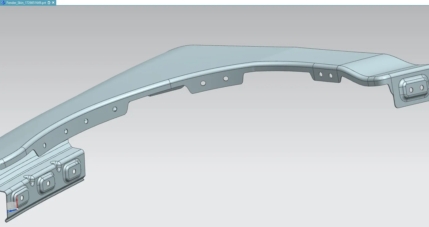
The baffle mounting, also known as the mudguard mounting, is located inside the wheel arch to protect the engine compartment from road debris and water splashes. The baffle is mounted using clip-fit plastic locking mechanisms for easy attachment and removal.
e. A-Pillar Mounting
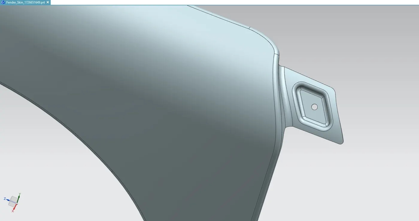
The A-pillar is a structural support that connects the roof and windshield frame to the vehicle body. The front fender is securely fastened to the A-pillar to enhance the vehicle’s rigidity and durability.
4. Manufacturing Process of the Fender
The manufacturing of a fender involves multiple sheet metal processes to achieve the desired shape, strength, and mounting precision.
a. Embossing
Embossing is a metal forming process used to create raised or sunken designs without altering the material thickness. This process enhances structural strength and aesthetics.
b. Bending
Bending involves applying force to deform sheet metal into a V or U shape. This is performed using mechanical, pneumatic, or hydraulic presses.
c. Cutting and Blanking
Cutting involves applying a shearing force to separate metal sheets into desired shapes. Blanking is a process where flat geometric shapes are punched out from a large sheet using a press and die system.
5. Main Design Considerations
a. Drip Area Design
The drip area mounting is attached to the engine compartment using weld nuts. The height of the drip area should be maintained at less than 40mm to reduce the spring-back effect during manufacturing and minimize NVH issues. Additional embossing and ribs are provided to increase strength and prevent deformations.
b. A-Pillar Design
The A-pillar area mounting is aligned with the windshield frame and roof structure of the car. This helps provide a robust structure for the fender and windshield assembly.
c. Bumper Mounting Design
The bumper mounting area is developed in consultation with the bumper design team to ensure perfect alignment with the fender and bumper.
d. Sill Mounting Design
The sill mounting area ensures a strong connection between the fender and the car body. Fasteners and embossing are provided to ensure a firm connection.
e. Baffle Mounting Design
The baffle mounting area is designed to protect against debris and water splashes during vehicle motion. Clip-fit plastic locking mechanisms are added for easy attachment and removal.
6. Results
A thickness of 0.75mm is applied to the surface to create a solid fender body. The fender is designed to comply with European wheel arch regulations and pedestrian safety standards.
The following NX CAD commands were utilized to model the fender:
1. Offset in Face
2. Curve on Surface
3. Trim Sheet
4. Law Extension
5. Datum Plane
6. Intersection Curves
7. Face Blend
8. Bridge Curve
9. Sketch
10. Projected Curve
11. Emboss
12. Edge Blend
13. Sew
14. Dart
15. Thicken
7. Conclusion
The front fender of the automobile was successfully developed by following the design constraints provided. The design includes provisions for mounting the fender to the body through bumper mounting, drip mounting, sill mounting, baffle mounting, and A-pillar mounting.
By designing a half-bumper type fender, material utilization was optimized, reducing scrap waste and manufacturing costs. The inclusion of ribs, embosses, and standard hole placement ensured a structurally sound and easily manufacturable fender design.
The final design complies with pedestrian safety regulations, ensuring that in case of minor accidents, pedestrian injuries are minimized. The fender also serves its primary purpose of protecting the engine compartment and improving aerodynamics.
References:
1. https://wuling.id/en/blog/autotips/get-to-know-more-about-car-fender-and-how-to-replace-it-if-it-is-damaged