Fender Design
Report :-
Flender is a part of automobile body which covers the wheel well so that mud,sand,rocks and liquids being throw into the air by rotating wheel into the air and prevent damage to pedestrian as well as car,this is placed over the wheel .
There are two types of fender long and short fenders in old cars like vintage cars there was long fender or also called full bumper type and short bumper type fender .
Full bumper typer fenders comsumes more material which increase overall weight of the vehicle and primary motive of the designer and manufacturer is reduce the weight of the vehicle .In half bumper type fender can produce two fender through one sheet by slightly increasing the size of the blank and also reduce the scrap rate.
Given :
Class A surface ,Master section
Mounting points:-
Drip Area : In drip area mounting there is minimum distance of 300mm form cowl mounting and 150mm form head lamp mounting can keep in between 300 but can not excess over it ,is important because it is mounted on engine component so care has to take that it will not create hurdle for installing the other components as well as while maintenance.
Splash Mounting :
The splash area also plays a vital role in anti chipping, it protect the dust particles,spray particles from being enter inside the car.thus splash plays vital role in the car.
Sill mount Area:It is the front potion of the fender where the bumper is mounted with the help of brackets.
A Pillar mounting :
A pillar is a region where the A Pillar of the car is mounted from the front fender.It is located at the top right corner of the fender.
Wheel Arch,Baffle and ORVM mount area Gap and Flushness requirement
Sill Area: it is located at the bottom corner of fender for proper holding of fender with body of the car.
Body :this is back potion of the fender which is directly connected to the body .
Cowl:this is made of plastic body in which motor of wipers are placed is usually bigger in size in all the automobiles but if the size of cowl diereses then can adjust the length of drift area.below the A piller mounting area.
GIVEN :
- Class A surface Area
- Master section
Class A surface is provided by design team to apply engineering features to it to fit it to the vehicle
Master section is provided for implementation of engineering features to it .
Drip area mounting:
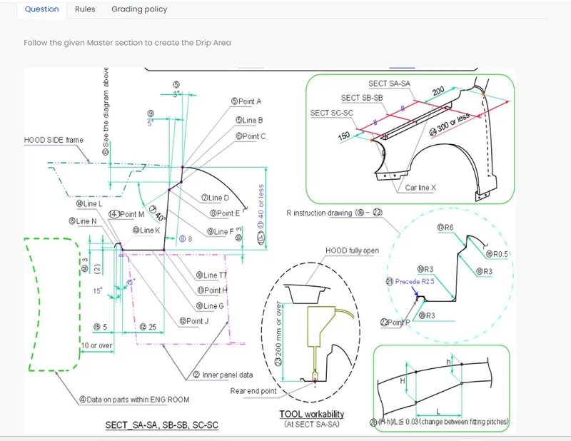
As per master section go to curve and select offset curve and took a mid line and offset it to a distance of 5mm down then go to curve on surface option and drew to curves and then trim off the excess portion to make flanges for mechanical operations .
In provided master section start from point A to point C called as line B and took a angle of 3deg ,this angle is taken because straight angle is difficult to manufacture
then again took 8mm line from point C to E called line D and then from point E to H took line F and angle of 40 deg and
then took a line of 17mm with an angle of 5 deg ie 85 deg down because when human eyes protrude inside the hood it should not see directly inside the hood (dirty portion )so this length must be less than 40 in some case it could increase up to 60 also but there it will cause spring back effect and also punch don’t go more than 30mm depth mostly .this 5deg angle is taken so that hood can open about 200mm to operate tool inside the engine compartment while fixing it properly.
Drew a horizontal line G from point H to J length of this line can not exceed above 35mm here it is taken as 25mm then one another line with 3mm height with 45deg taken and then then with length of 5mm a horizontal line is taken and then with 15 deg angle a 2mm line is taken.
Above this length we can not install any component about 10 mm distance for proper operation of tool.Filets are provided to reduce all the sharp corners.
A Pillar Mounting :
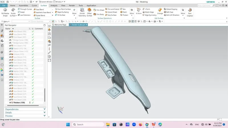
In an A Pillar mounting took a curve on surface and drew two curves and trimmed them to get flange and then drew a line connection to two points and used law extension commnd and extend it up to 45mm then used extend command and extend both the surfaces by 5mm at least and then by using trim and extend command trimmed off excess portion to get desired A Pillar mounting .
Took a datum plane choosed 3 point plane and then choose sketch and plane as surface and select vector direction and then drew a rectangle then project it on surface and embossed by using embossing command by distance of 3.5 mm and by selecting plane as datum plane .then again drew a circle and trimmed it from embossed potion while taking circle drew two circle one of 5mm radius and another one is of 10mm radius make it as reference this one is for clearance that is around the hole there must be 10mm clearance for proper fitting of bolts.
By using curve on surface option reliefs are provided.
By using bridges curve option R3 corners provided.
Filets are provided to reduce all the sharp corners.
Seal Area Mounting :
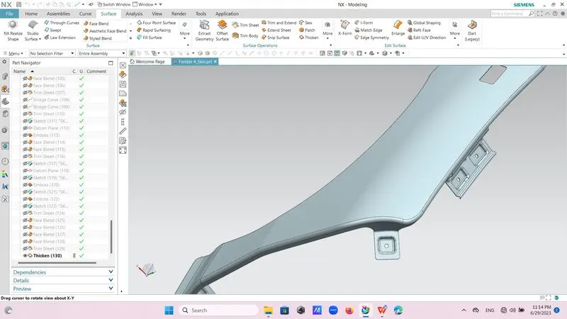
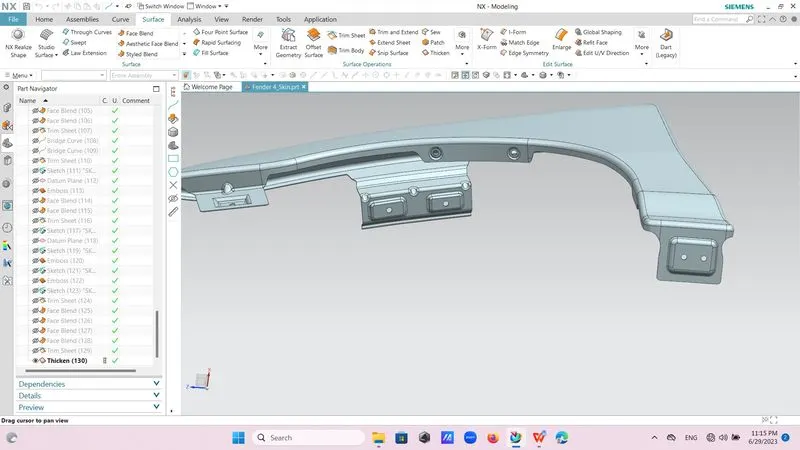
In this Area used curve on surface option and trimmed the surfaces as per requirement and then used extended sheet option and extend it up to 35 mm and then took a datum plane as 3 point and then drew a sketch on it for embossed surface and constrained it go to surface then more and crossed embossed command and embossed it by depth of 3.5mm with 12 deg draft then drew new sketch of two circles and trimmed them through out the surface in one direction.
By using curve on surface option reliefs are provided.
By using bridges curve option R3 corners provided.
Filets are provided to reduce all the sharp corners.
Hood Body Mounting :
Same above used curve on surface option and then trimmed it to get flange and drew a line then extend it about 40mm and then by using extend option form surface extend both the edges by 5mm and then by using trim and extend option and trimmed off excess portion of the surface. Them by using face fillet give it fillet .
By using curve on surface option reliefs are provided.
By using bridges curve option R3 corners provided.
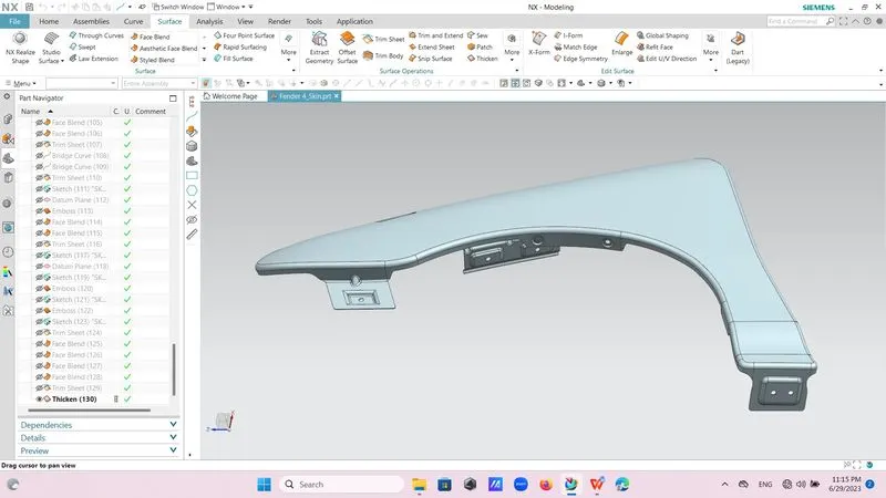
Filets are provided to reduce all the sharp corners.
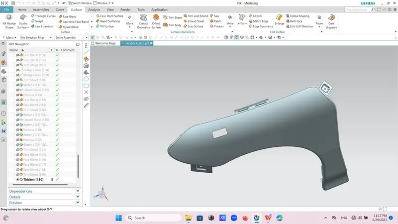
wheel arch mounting two holes are created.
For ORVM installation rectangular hole is created
Thick :
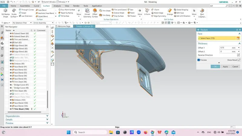
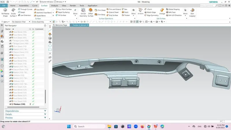
Now go to surface and then thick command and thicken this surface by distance of 0.75mm,outward direction.