Fender Design
AIM :-
From the given Master section to create the Drip Area.
For the Sill, Bumper, Baffle(Splash), and A-Pillar mount create your own design according to the Engineering standard that you learned. & need to
create a report with all the relevant images included for the mounting points created.
The fender seimens part file has provided . That is the skin data where we need to work & make as a Different mounting area as :
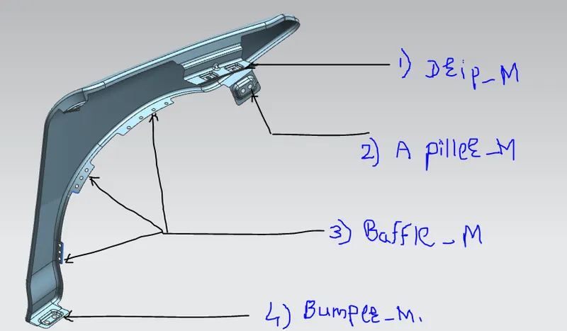
- Drip Area
- A piller mounting
- Baffle mounting
- Bumper mounting.
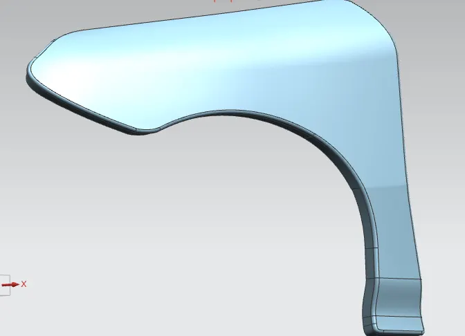
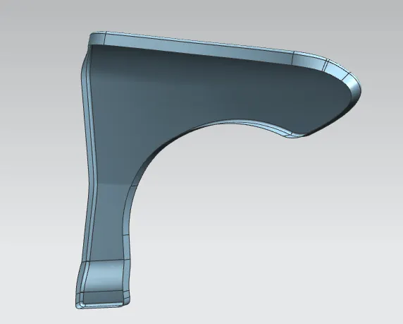
So step by step we move forward to make a mounting at required position & place followed by the Mater_sections.
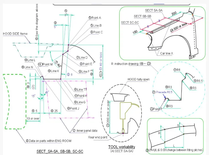
PROCEDURE_1 :- Creation Drip mounting Area
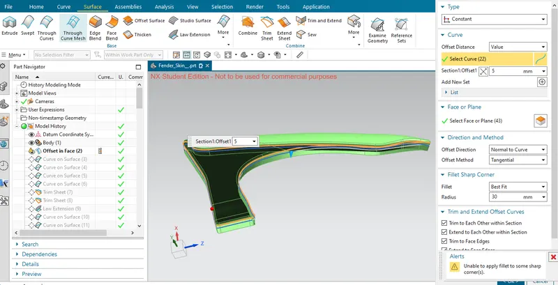
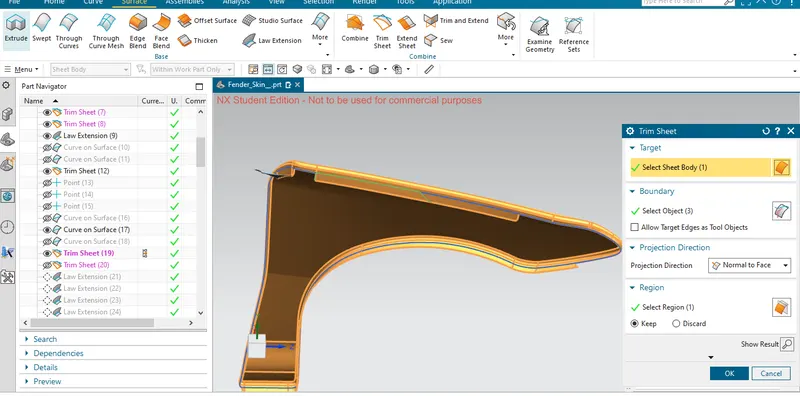
First we need to offset a curve ay a proper distance & required for the mountings makiing. Here i have tajen a offset of that curve from top to little bit downward as 5 mm. Follow that curve & make a curve on surface for the mountings. After creating the curves at various position we need to trim the sheets for getting a proper mounting location.
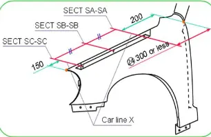
Here first to note that we need to keep a distance front end that is 150 mm & at rear end is 200 mm apart feom the Drip mounting region. It is the biggest consideration of the master section.
After getting a proper position for the drip mounting we need to create a law extension to grow up that region by followed by master section.
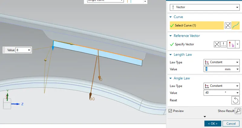
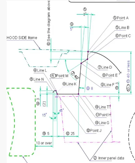
The multiple law extensions are created to getting a proper mounting by taking a referance of the master section.
- The first law extension are created ata distance 8 mm with 90 degree to the base of the flange.
- Second is created 40 mm from the top diamension consider that is exactly from first law extension is 17 mm & 4o degree angle.
- Third is created as 25 mm an 90 degree
- Furth is 4.24 with an 45 degree
- Fifth is 1.5 at an angle is 0 degree that is parallel to the horizontal plane
- & final is 2 mm with 75 degree to the horizontal or 15 degree to the vertical as well.
The finally created the roughh mounting as ;
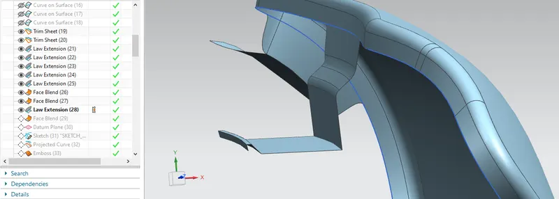
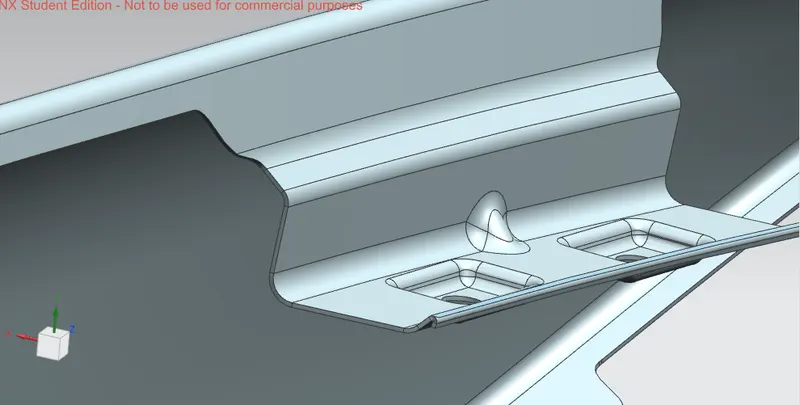
provide the face blend & Create an Emboss over the flate surface to the exact mounting position of the Drip side.
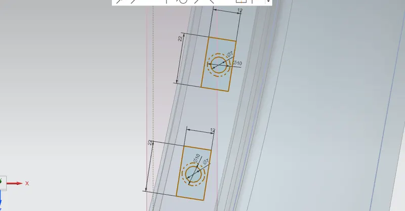
After creating the sketch of the Emboss we need to transfer this sketch means of project the curve on the surface. After that we need to make a emboss over it with an 3.5 mm as per the design rule.
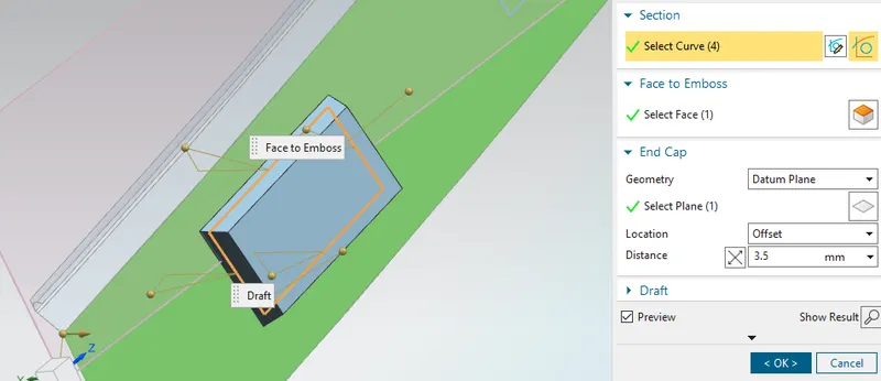
After making a emboss we need to provide a blends with an 3+ Tickness of the fender so we need to provide it exactly is 3.75 as well. The mounting hole has created by creatinng the sketch & same procedure that we need to project the curve & apply a trim sheet command. So we get a peoper emboss with mounting hole.
We moving final step of the Drip mounting area to provide it strength. Hence we create a DART here to make part stength & finally provide the edge bends over remaining area.
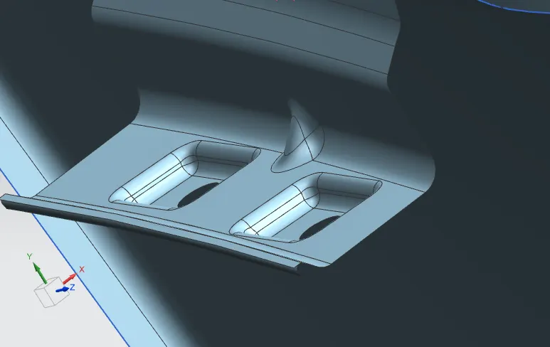
In this way the same procedure is applied to making a A piller mounting & bumper mountings.
2. PROCEDURE_2 :- A piller mounting region.
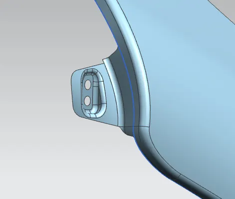
3. PROCEDURE_3 :- Bumper mounting
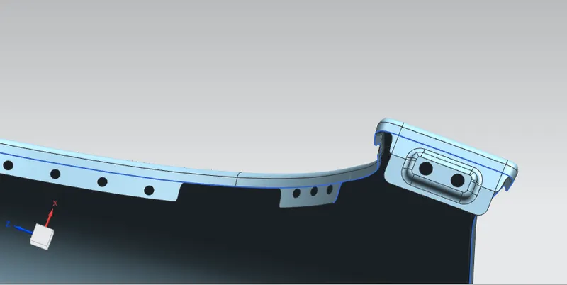
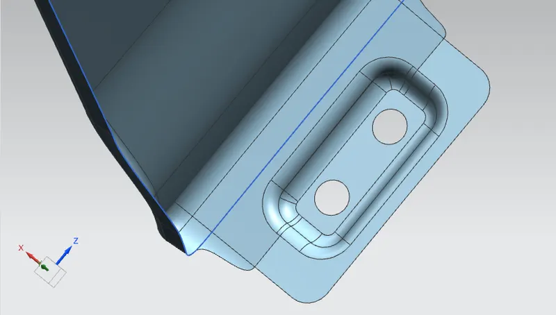
4. PROCEDURE_4 :- Baffle mounting
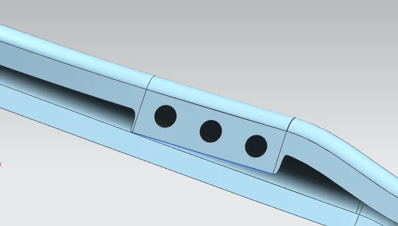
Except of this region no need to create any emboss or extra feature simply creates a mounting holes. Because no any rigid parts are linked to this regiono for the cration emboss, so the holes are sufficient by the design rule.
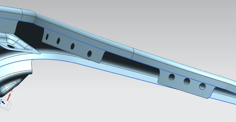
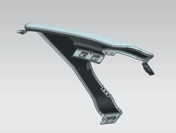
After completing all region mounting we need to Thicken the part an 0.75 mm .
CONCLUSION :-
In this way i have created all the required mountiing of the fender from reference of the given Master section to created the Drip Area For the Sill, Bumper, Baffle(Splash), and A-Pillar mount create your own design according to the Engineering standard has learned & created a report with all the relevant images included for the mounting points created. Finally the seimens part file is attached to the challenge.
Thank You.