Fender Design
FENDER DESIGN
AIM:To create a fender side part and its mountings as per the given master section and also according to the requirements using the given styling surface
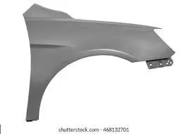
FENDER
- Fender is the American English term for the part of an automobile, motorcycle or other vehicle body that frames a wheel well (the fender underside). Its primary purpose is to prevent sand, mud, rocks, liquids, and other road spray from being thrown into the air by the rotating tire.Whici in turn also prevent these debrises from getting into other automobiles and also from the pedestrians.
- Considering the design and manufacturing feasibility,the fender should be made in such a way that it should have necessary clearance between wheel and wheel arc consdiering which regulation we are following.There are three main regualations which is followed worldwide which are japanese regulations,european regulations and american regulations.
- Mountings should be created in sill area,baffle mount,bumper side,A pillar side and drip area
ASSEMBLY
Top down approach:
- In the top assembly design approach, components are created inside the assembly design workbench . There is no need to create separate part files of the components. This design approach is completely different from the bottom-up design approach. Here you have to create the product file first and then one by one create all the components. They are saved and opened individually one by one when they are needed . Here the construction and the assembly takes place simultaneously which makes easy for the one who works on it to completely work on each parts together.
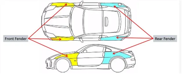
TYPES OF FENDERS
Mainly there are four parts at which fenders are used and there is two types of fenders that are used;
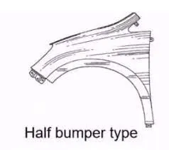
- Half bumper type:Half Bumper Type fenders are widely used now, due to its mini size and the scrap or wastage is less compared to the full bumper type and also its feasibility of any repairs that may have to be carried out after any accident that might happen with frontal impact
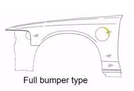
- Full bumper type:This type of fender is used in olden days, it is no more in use due to its heavyweight of the structure and consumes more raw material in manufacturing.
MANUFACTURING PROCESSES
The manufacturing of the fender majorly involves these operations.
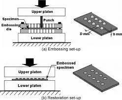
Embossing
Embossing is a metal forming process for producing raised or sunken designs or relief in sheet material using matched male and female roller dies, theoretically with no change in metal thickness, or by passing sheet or a strip of metal between rolls of the desired pattern.
Bending
Metal bending is a process by which metal can be deformed when applying force to the subject, which causes it to bend at an angle and form the anticipated shape, which often results in it being in a ‘V’ or a ‘U’ shape. This is done through the application of force on a workpiece. The force on the work piece can be mechanical, pneumatic or hydraulic.
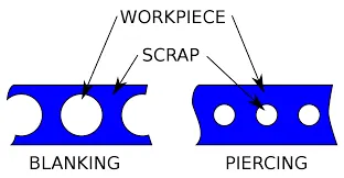
Cutting and Blanking
Cutting and blanking have the same process but the output that is needed is different in both
Cutting processes are those in which a piece of sheet metal is separated by applying a great enough shearing force to cause the material to fail.
Blanking is a steel manufacturing process in which a flat, geometric shape is created by feeding a coil of sheet metal into a press and die. In this process, the blank is punched out from the large metal sheet.
MOUNTING REGIONS ON FENDER :
- SILL AREA MOUNT
- BAFFLE MOUNT AREA
- BUMPER MOUNT AREA
- A PILLAR SIDE MOUNT
- DRIP AREA MOUNT
SILL AREA MOUNT
The area at which the bottom of the fender gets connected to the floor near the bottom edge of the door. The Embossed sill mounting of the fender is attached with the fasteners.
- The inner boundary of the wall is offsetd to 5mm and then splitted
- Then extrapolate the part that,where we need to create a mount and using spline avoid any sharp edges
- Then extrapolate more to create the emboss
- Create the emboss by creating a sketch on the surface and also creating another flat surface below that with an offset of 6mm
- Sweep the sketch using ref.surface and then apply edge fillets to it before using shape fillet to create the final output.The shape fillet should be 3+thickness

BAFFLE MOUNT AREA
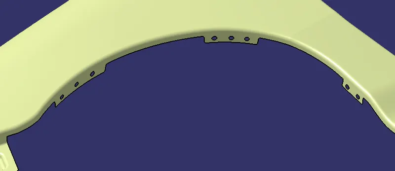
In this region, the baffle gets installed to the fender with the help of clips which holds the baffle with the fender along the wheel arch.
- Here you have to extrapolate the parts where you need to create the mounts and then create holes on it
- Using spline you have to avoid sharp edges
BUMPER MOUNT AREA
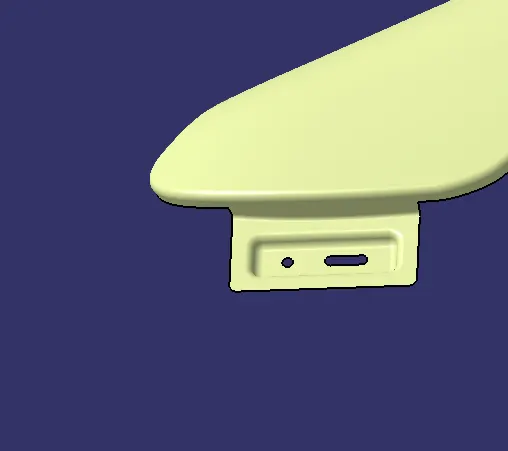
The bumper mounting region is located beneath the bumper. The fender gets attached before the installation of the bumper. After fixing the fender with fasteners the bumper will cover the bumper mounting.
- Extrapolate the part where you need to create the mount
- Create the sweep using the edge
- Then create emboss by making sure it also has a flat surface as we have created earlier
- For bumper part mounting a slot and an hole is appropriate
A PILLAR SIDE MOUNT
This Mounting region is located near the cowl of the vehicle where the fender is fastened with the bottom edge of the windshield. This mounting is covered with the side rear-view mirror.
- Here also the mounting should be created by following the same process that we followed earlier to create sill mount and bumper mount
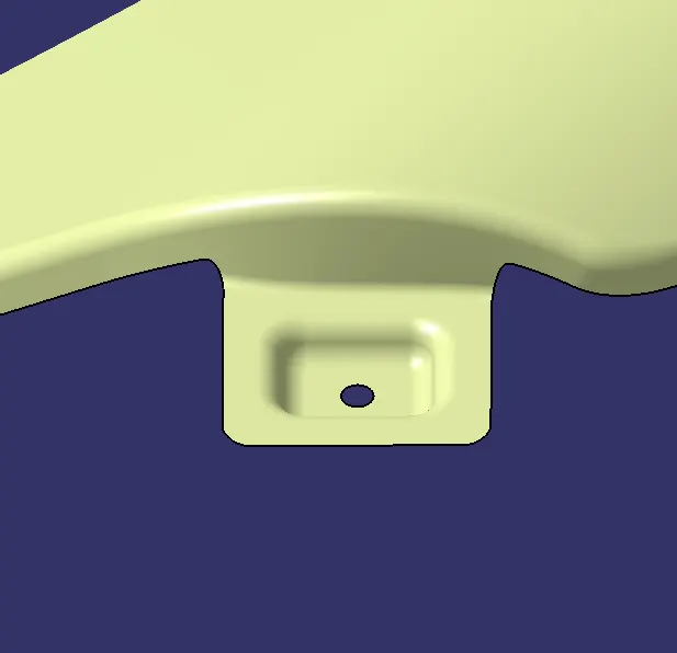
DRIP AREA MOUNT
The area at which the fender gets attached to the engine housing through fasteners. It is the major mounting for the fender. Mountings at the drip area are designed leaving a clearance of 200mm from the back of the fender for the cowl setup. And clearance of 150mm from the front of the fender for a headlamp housing unit.
The drip area mounting should be created by following the master section given to follow the design considerations and to create a proper mounting.
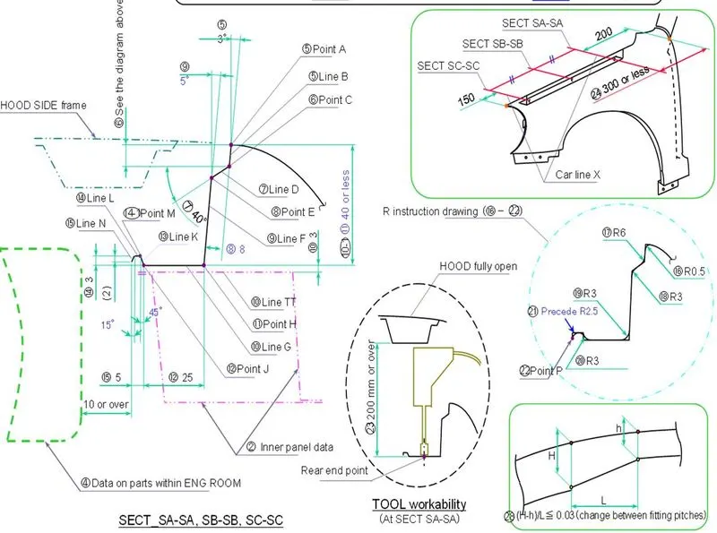
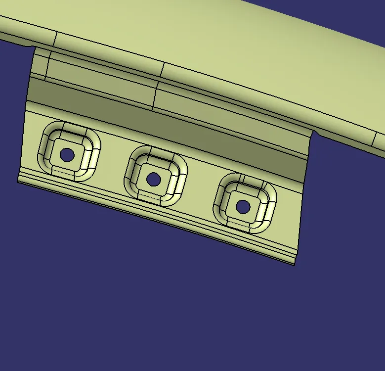
- For drip area mount,create sweeps using the edges with draft direction by using X,Y,Z axes with given angles
- Find out the measures of sides using anglers given by using trigonometry
- Give edge fillets and shape fillets(bi-tangent,Tri-tangent)accordingly
- Give necessary reliefs to corners after creating fillets
- create embosses by keeping the surfaces flat
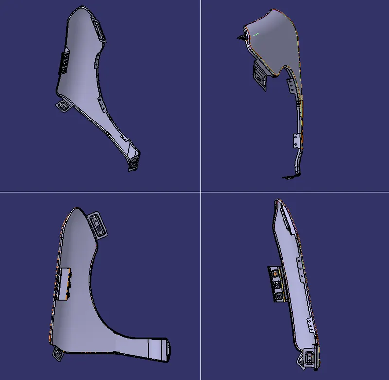
THICKENED PART
CONCLUSION
- We designed five different mountings at sill area,baffle mount area,bumper side area,A pillar side and drip area by following the design considerations and by following the given master sections on the fender so that it can be mounted to other parts easily with better tooling feasibility