Fender Design
AIM:
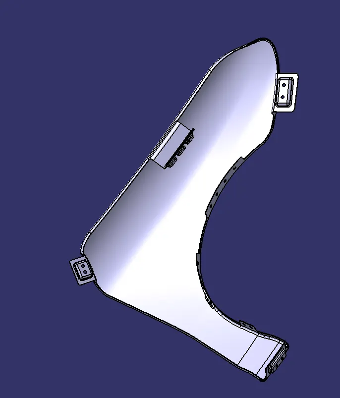
- To design the various mountings on the fender such as Sill mounting, A-pillar mounting, Bumper Mounting, Baffle mounting and Drip area mounting according to the given design parameters.
INTRODUCTION
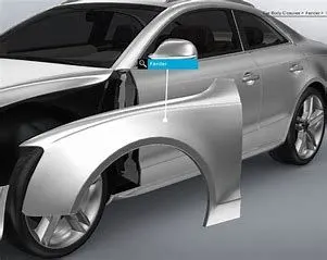
- Fender is a part of a car. Its primary purpose is to prevent sand, mud, rocks, liquids, and other road spray from being thrown into the air by the rotating tire.
- Most passenger automobiles have four fenders, one over each wheel. For vehicles with a narrow car body that exposes the tire, the fender is an exposed curve over the top of the tire. For wide body vehicles that cover the tire, the fender forms the wheel well surrounding the tire, and is not directly visible from above the car body.
TYPES OF FENDERS
- Full bumper type fender
- Half bumper type fender
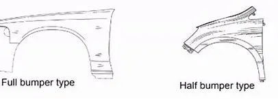
FULL BUMPER TYPE FENDER
- This type fender was used in early days whether It’s used to cover the full area in the front till the front lights. However, it has a lot of extra material which increases weight of the car. Hence, this type of fenders is no longer used in automobiles.
HALF BUMPER TYPE FENDER
- This type of fender is most used in automobiles. Here, the scrap is decreased by huge amount. As, in the full bumper, we could only produce one fender per blank, where as it is feasible to produce 2 fenders per blank in case of half bumper type which leads to scrap management.
MANUFACTURING PROCESSES
- Embossing
- Cutting
- Bending
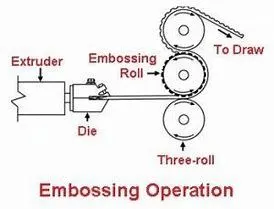
EMBOSSING OPERATION
- It is a metal forming process for producing raised or sunken designs or relief in sheet material using matched male and female roller dies, theoretically with no change in metal thickness, or by passing sheet or a strip of metal between rolls of the desired pattern.

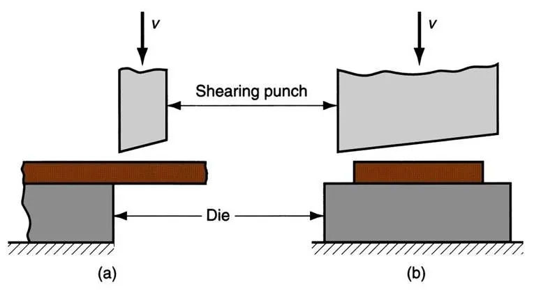
CUTTING OPERATION
- Cutting processes are those in which a piece of sheet metal is separated by applying a great enough shearing force to cause the material to fail.
BENDING OPERATION
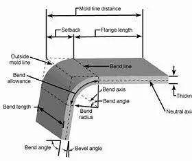
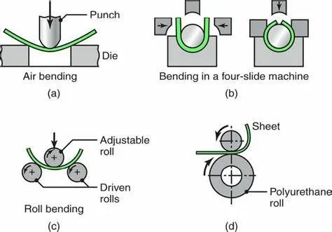
- Metal bending is a process by which metal can be deformed when applying force to the subject, which causes it to bend at an angle and form the anticipated shape, which often results in it being in a ‘V’ or a ‘U’ shape. This is done through the application of force on a workpiece. The force on the work piece can be mechanical, pneumatic or hydraulic.
DIFFERENT MOUNTING REGIONS ON FENDER
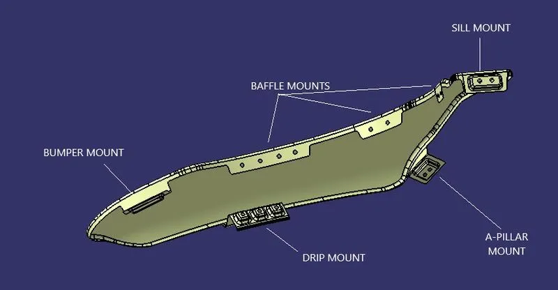
There are five regions where mountings are mounted on the fender. They are
- Sill mounting
- Baffle mounting
- A- pillar mounting
- Bumper mounting
- Drip mounting
PROCEDURE
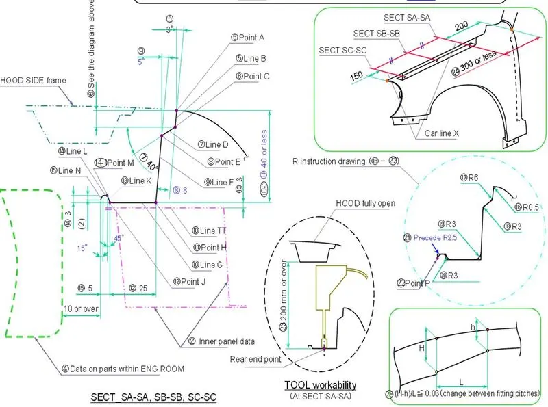
Data To Be Considered While Designing Drip Mount:
- First, import the given reference into the workbench. Then join all the surfaces using join feature.
- Check for any connectivity error by creating boundary using boundary feature.
- Check for any repair work. If there is any, repair those dark black lines by extracting those lines first and splitting it with the help of split feature. And finally, using multiple section surface feature on those split areas.
- Offset the outer edge by extracting and use parallel curve feature to the distance of 5 mm and then use split on that line.
- Then, start creating those mountings on their respective regions.
- Extrapolate themount region by using extrapolate feature. Then use spline option on the edges of the extrapolated surface to create a smooth edge.
- Create a plane parallel to the surface to draw the sketch for emboss. Sweep the sketch with respect to the reference surface with angle of 7 degrees.
- Create a plane using offset with a distance of 6 mm from the emboss plane. There draw a line and extrude it for the emboss slat surface.
- Holes are made with the standards. We used M5 holes.
- Then give shape fillet of about 3.75 mm radius to the sharp edges of the emboss.
- Finally. use thicken method to the final surface with the 0.75 mm inside direction.
SILL MOUNTING
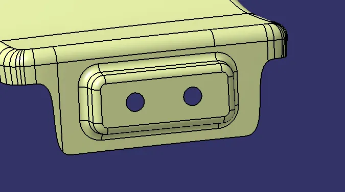
- The vehicle body suffers from various kinds of externally derived forces such as vertical bends and longitudinal twists which act around the axis of the vehicle body, a prerequisite is that those portions of the vehicle body which surround the door openings, especially the lower portion, be provided with sufficient rigidity.
- This prerequisite is generally met by using side sills which are individually located at a lower right and a lower left portion of a vehicle body in such a manner as to extend in the longitudinal direction of the vehicle body. The side sills which serve as reinforcing members for insuring the rigidity of the vehicle body around the door openings.
BAFFEL MOUNTING
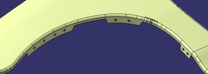
- For stopping all the debris entering into the engine room and other components splash protector mountings is been introduced. It just requires a area to hold the splash protector, so holes or slots are provided as per requirement.
A-PILLAR MOUNTING
- They are important for hiding glass in place and adding structural integrity to a vehicle, primarily the roof. The A pillar holds the windshield in Place. B pillar at the end of the first door. They usually offer substantial structural support for a vehicle's roof. Most of the time they are bound to the body frame and wrap all the way into the roof. Depending on the design, there may be multiple pieces attached to increase integrity of the roof. They are also responsible for where a door's latch connects to the body. C Pillar hold a vehicle's rear window in place.

BUMPER MOUNTING
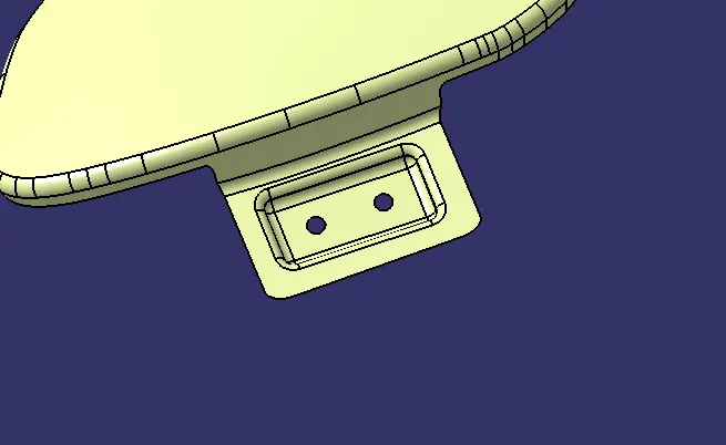
- Bumper is a structure attached to or integrated with the front and rear ends of an automobile to absorb impact in collision, ideally minimizing repair costs. They are increasingly being designed to mitigate injury to pedestrians struck by cars, such as through the use of bumper covers made of flexible materials.
- For the bumper the mounting are made to fix with the bumper to give sufficient strength and to withhold the mating parts. Front bumpers especially have been lowered and made of softer materials, such as foams, crushable plastics to reduce the severity of impact on legs.
DRIP MOUNTING
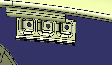
- The basic design of a fender involves in developing the drip area as it is a major mounting region and requires certain considerations to meet the standard values. This design takes a vital role for maintaining the proper gap between hood and the fender which shouldn't be visible for human eye.
THICKENED SURFACE
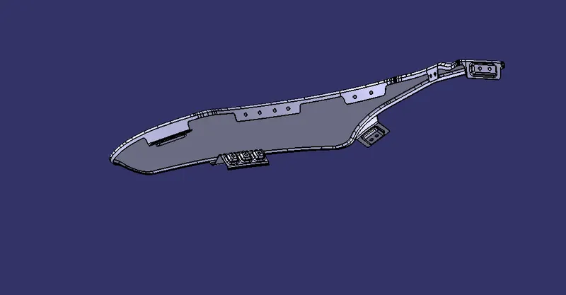
MULTIPLE VIEWS
FRONT VIEW
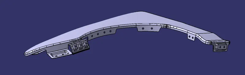
SIDE VIEW
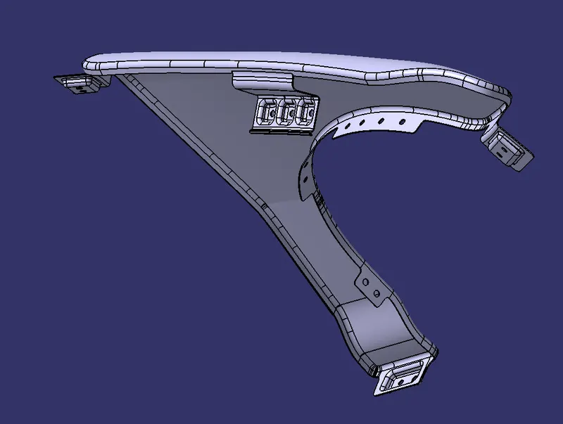
TOP VIEW
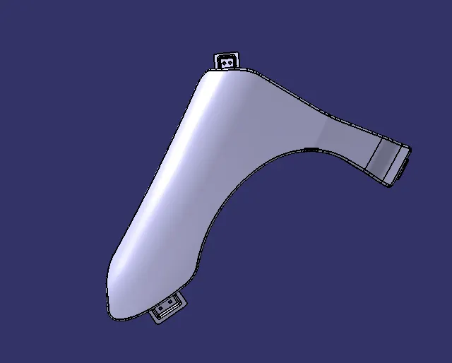
BOTTOM VIEW
CONCLUSION
- Thus the different mountings such as sill, baffle, A-pillar, bumper and drip area mountings are designed in the fender according to the standards and master-section provided.