Fender Design
Challenge: Create mounting Provisions for the given fender Model as per input & design guidelines.
Ans:
Fender
Fender is the American English term for the part of an automobile, motorcycle, or other vehicle body that frames a wheel well (the fender underside).
Its primary purpose is to prevent sand, mud, rocks, liquids, and another road spray from being thrown into the air by the rotating tire. Fenders are typically rigid and can be damaged by contact with the road surface.
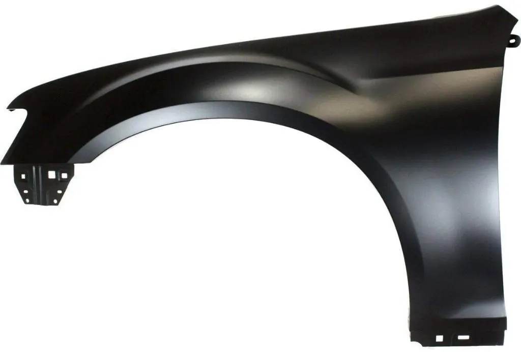
Fig 1: Fender
Sticky materials, such as mud, may adhere to the smooth outer tire surface, while smooth loose objects, such as stones, can become temporarily embedded in the tread grooves as the tire rolls over the ground. These materials can be ejected from the surface of the tire at high velocity as the tire imparts kinetic energy to the attached objects. For a vehicle moving forward, the top of the tire is rotating upward and forward and can throw objects into the air at other vehicles or pedestrians in front of the vehicle.
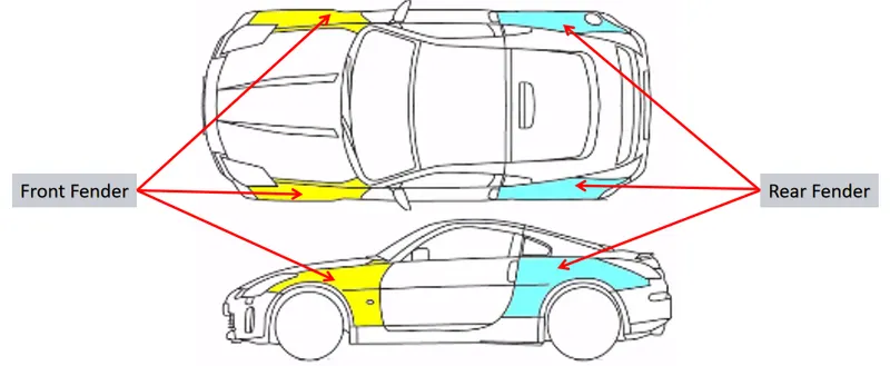
Fig 2: Front & Rear Fender
The above image illustrates the position of the fenders. Generally, a car will have 4 fenders each per wheel.
TYPES OF FENDERS
1. FULL BUMPER TYPE
It is the traditional type of fender used in earlier models of vehicles. As it is a Full bumper type, needs big sheets to make the parts. There is less scope for scrap management during production. And the weight of the fender is also more, as we know the weight of the car plays a very important role in performance & efficiency of the car.
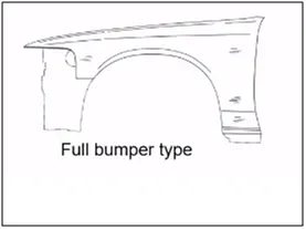

Fig 3: Full Bumper Fender
2. HALF BUMPER TYPE:
In order to decrease the fender weight & to simplify the design complexity, half bumper type of fenders were introduced. These fenders are mainly used for serving the purpose of cost-cutting and reducing enough proportions of the steel weight resulting in a reduction of the weight of the vehicle slightly. They can be economically manufactured, i.e by slightly increasing the blank size, we can produce two fenders at a time.
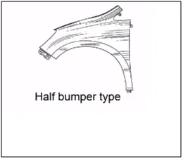

Fig 4: Half Bumper Fender
Generally, Feder is connected to 5 different components, Each area needs mounting provisions to assemble the fender with other parts. Below are the areas in which the fender will be assembled.
- Drip Area
- Bumper
- Baffle
- Body
- Sill
- A-Pillar
In recent times no provisions are making at the body area as it is becoming an obstacle for the door hinge.
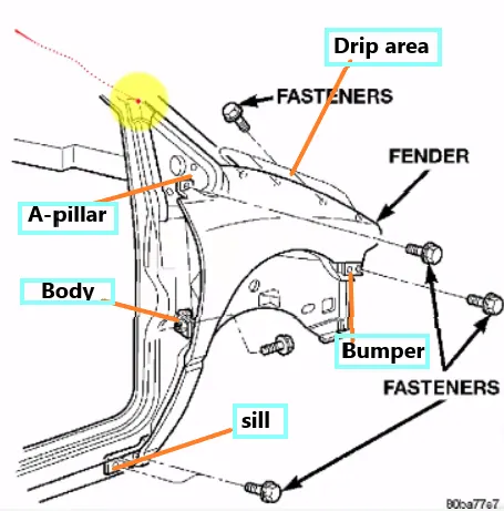
Fig 5: Fender Mounting locations
Inputs given
A CAD model of the fender is given
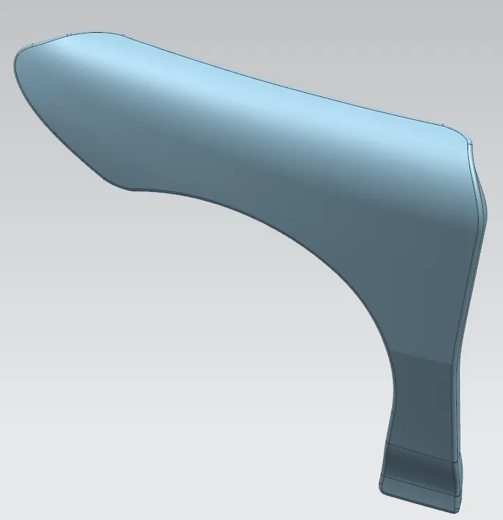
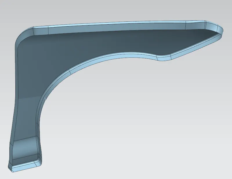
Fig 6: Given Fender Model
Drip Area
The drip is the area where the fender is assembled to the engine housing using fasteners.
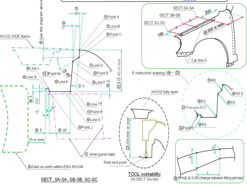
Fig 7: Master section to create mounting provisions at Drip Area
All the design requirements shown in the master section are followed to create flanges.
- Flange is created as per the master section given.
- Distance between the A-Pillar endpoint & Flange is 150mm.
- Distance between the front lap endpoint & Flange is also 150mm.
- A plane is created using 3 point method and used to create a profile for the embossing operation.
- Sketch projected on the flange & emboss created.
- Darts are created to increase flange strength & stability.
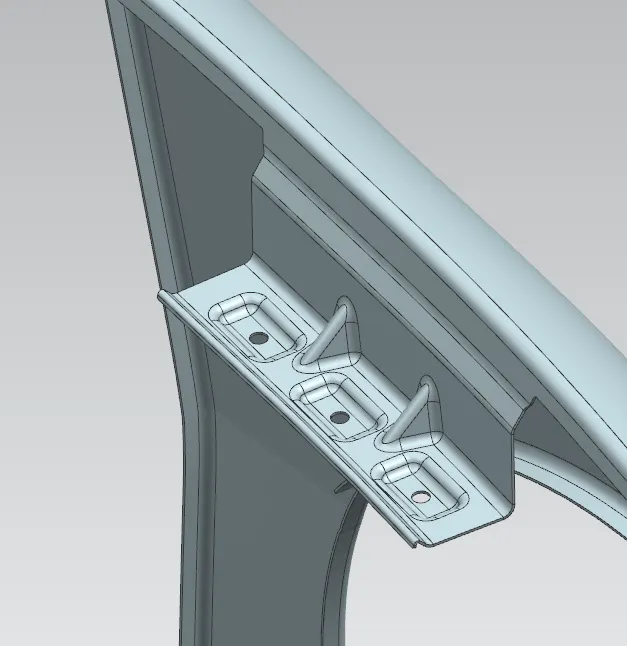
Fig 8: Fender mounting provisions at Drip Area
Bumper Area
A similar procedure was followed to create mounting provisions at Bumper Area
- Flange is created with approximate length.
- A plane is created using 3 point method and used to create a profile for the embossing operation.
- Sketch projected on the flange & emboss created.
- Dart is created to increase flange strength & stability.
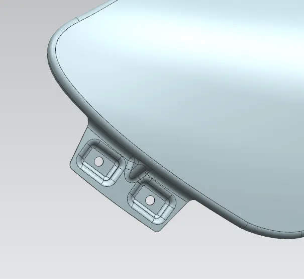
Fig 9: Fender mounting provisions at Drip Area
Baffle Area
Baffle is mostly made of plastic which is used to improve the NVH of the car. It also protects the engine parts from mud & stones similar to fender.
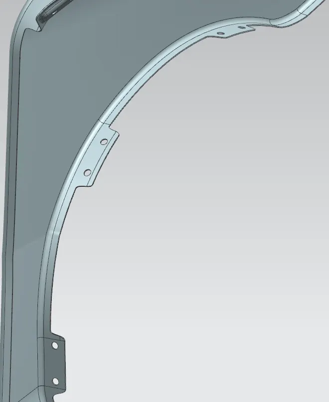
Fig 10: Fender mounting provisions at Baffle Area
Sill Area
Sill is the area located bottom side of the front door. The bottom side of the fender is assembled to the door supporting flange.
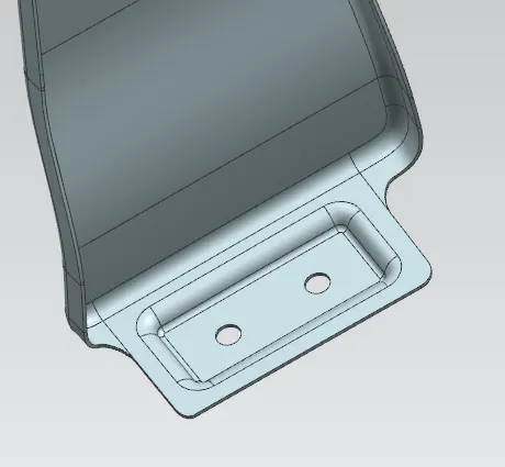
Fig 11: Fender mounting provisions at Sill Area
A-Pillar Area
It is the structural member which connects the roof & engine housing. The A-pillar provides support to the windshield of the vehicle.
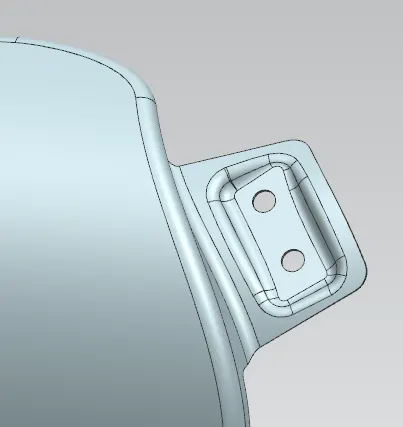
Fig 11: Fender mounting provisions at A-Pillar area
After creating all the mounting provisions, the model thickened by 0.75mm.
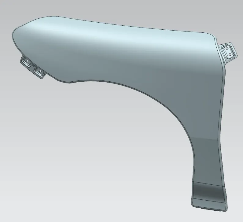
Fig 11: View-1
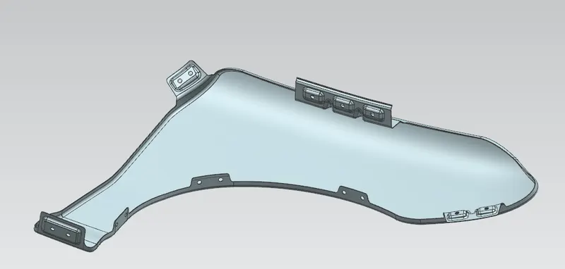
Fig 11: View-2
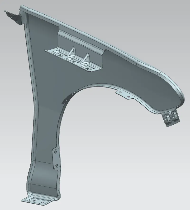
Fig 11: View-3
Conclusion: All the mounting provisions for the given fender model are created as per input & design guidelines.