Fender Design
AIM :- To Design a fender and its mounting by using a given fender skin & master section for wheel arch by using NX CAD as per engineering design standard.
OBJECTIVE :-
- Design a front fender from the given skin data and the master section provided with Drip mounting, A-pillar, Sill, Bumper and Baffle (splash) Mounts
- Prepare a report by explaining about Fender Design and its different mounts , manufacturing process and its design parameters
FENDER :-
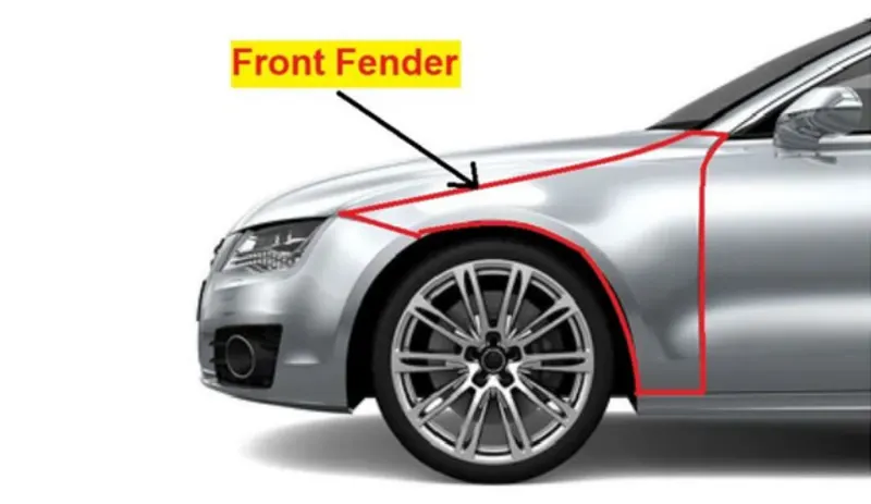
- Fender is the American English term for the part of an automobile, motorcycle or other vehicle body that frames a wheel well (the fender underside). Its primary purpose is to prevent sand, mud, rocks, liquids, and other road spray from being thrown into the air by the rotating tire.
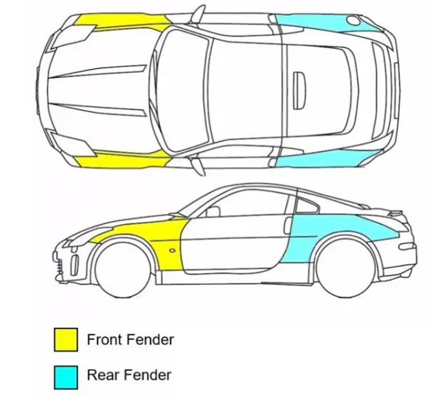
- The fenders are located over the wheels of the vehicle – two in the front right and left, and two in the rear right and left of your vehicle.
- Fender is a closure component, closing the engine compartment and other compartments. The major role of the fender is to avoid the chipping inside the engine compartment. During the motion the wheel picks a sand mud and small stone particles and throws it inside the car and these fenders will be helpful in preventing them by hitting inside the engine compartment and car body. These fenders will have a plastic part which lies on wheel arch area. The fender plays a major role to avoid problems for pedestrian also.Fender are typically rigid and can be damaged by contact with the road surface. It is often also called as Mudguard.
TYPE OF FENDER :-
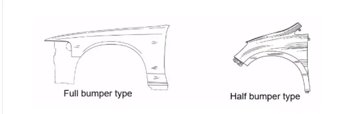
- Full Bumper Type
- Half Bumper Type
FULL BUMPER TYPE :-
The full bumper type fender was used in old cars, it covers the full area until the front lighting. But it has a lot of sheet metal material which is unnecessary and increases the weight of the fender. This type of fenders are no longer used in automobiles.
HALF BUMPER TYPE :-
Now a days half bumper type is used in automobiles. It is basically related to scrap management. Half bumper type leads to less wastage of the blank. Half bumper type is the modern design where less material consumption is observed, so productivity increases by reducing the size of the blank and thus providing more performance. The maintenance also relatively low compared to the full bumper type. We are changed from full bumper type to half bumper type to reduce the scrap rate per blank. In the full bumper, we can only produce one Fender per blank, whereas as a half bumper type we can produce 2 fenders per blank.
FENDER WHEEL ARCH :-
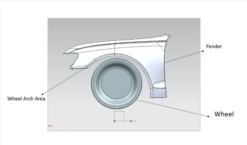
- Wheel Arch is the semi-circular part of the fender positioned above the wheel of the vehicle.
- The design of the wheel arch of the fender should be such that it must shield wheels and protect both passengers compartment and pedestrians from the projection of water, mud and stones.
- The wheel arch area of the fender is usually designed as a cover or shield over the tyre along its perimeter to stop any debris or stones, dirt, sand, snow etc….from getting thrown into the vehicle or the BIW area as well as outside the vehicle and onto other vehicles or pedestrians on the road.
- For the vehicle to has its permit in different countries, the wheel arch of fenders must be compliant with the standards and regulations set by respective countries.
MOUNTING REGIONS IN A FENDER :-
There are generally 5 mounting regions on a Front fender-
- Drip area mounting
- A-Pillar mounting
- Sill mounting
- Cowl mounting
- Body mounting
DESIGN CONSIDERATION:-
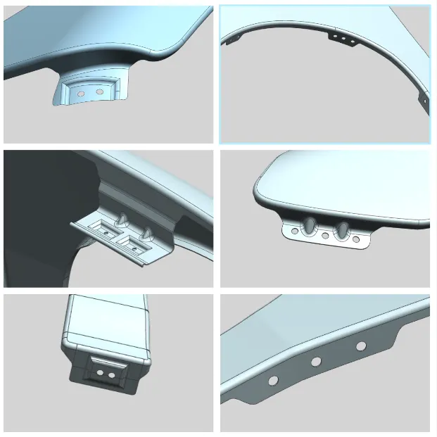
Design Fender Mounting areas by following the Master Section mentioned with the Design parameters. Drip Area mounting according to given parameters and for Sill, Bumper, Baffle (Splash), and A-Pillar mounting creating my own design according to the Engineering standard.
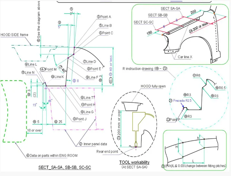
1. Design 0f Drip area mounting :
- Considering the above design constrains we have to design the drip area. Embosses are provided to increase strength, corners of the flanges are smoothen to ease of the production. Uniform wall thickness of 0.75mm.
- It is the important mounting of the fender which is connected with the engine compartment, therefore the lot of design constraints are to be followed while designing the fender
- For designing of drip area initially leave 200-300 mm for cowl top.
- For a headlamp need to leave at least 150 mm at the front while designing the fender
- Initially 3-degree angle and 9mm length is given while creating a drip area because the engine component should not be visible from outside.
- Cowl top part consists pf wiper motor and its instruments
- Embossing are provided on the mounting to strengthen them during fastening
- A rigidity bead is provided at the end to increase the strength of the mounting.
- The depth of the drift should be between 40 to 60mm. If the depth exceeds from 60mm then forming is not feasible due to spring back and wrinkles.
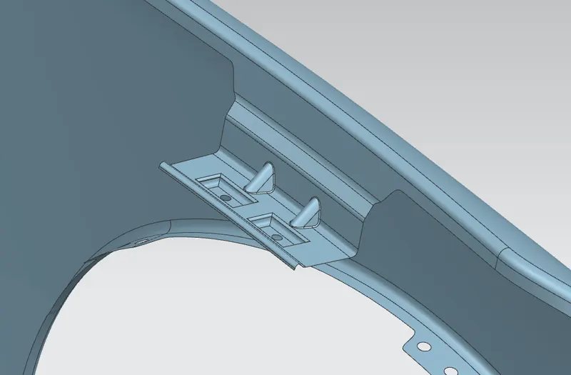
2. Design of A-pillar mounting area :
- The A -pillar is the structural pillar that combines the body to the roof . this make the sides of the wind shield rest
- The A-pillar area mounting depends upon the pillar of the car. the mounting can also be provided with ribs to strengthen the part. this mounting is critical in design as it has to be mounted on A-pillar properly.
- It is Mounted on the A Pillar by means of fasteners and these are covered by outer side view mirrors.
- Here, the proper embossing are provided along with holes for fasteners.
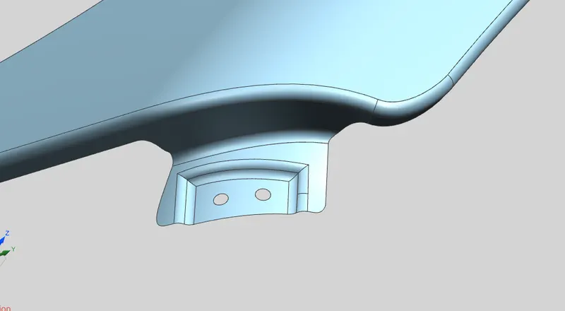
3. Design of Sill Mounting Area :-
- Sill is the panel which is directly below the bottom of the door supporting the floor and may be used to combine the floor and the body .
- The Sill Mounting area is in the bottom of the fender. It is mostely gets connected with the door region of the car.Here, proper embossing and holes for the fasteners are provided.
- this mounting point is basically on the bottom of the fender . the mounting part should be created such that the fender is firmly attached to the sill. The sill mounting position is designed with holes and emboss .
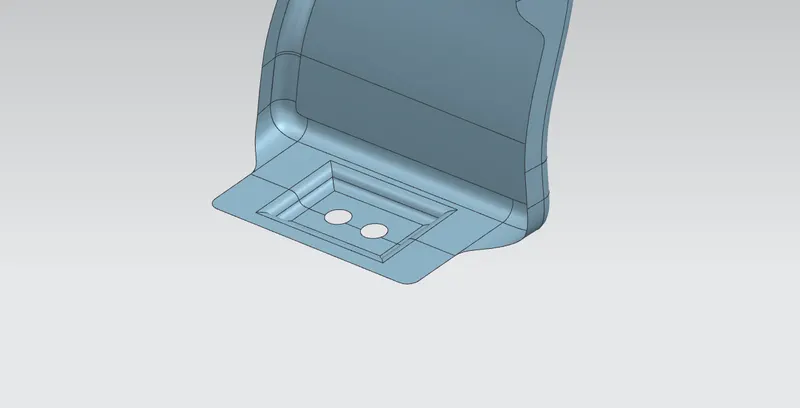
4. Bumper/Cowl Mounting Area :-
In this Mounting, the Fender connects with the bumper.
The Bumper Mounting region must be rigid in order to withstand the force acting upon it during collision. So, the Mounting space can be larger
Sometimes fender is also provided with the cowl area mounting. this mounting is on the top side of the fender. It is used to fix plastic bumper to the fender with the help of the fasteners.
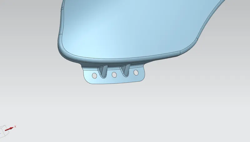
5. Body mounting
Body mounting is also created to mount the fender along with the hinges of the door.
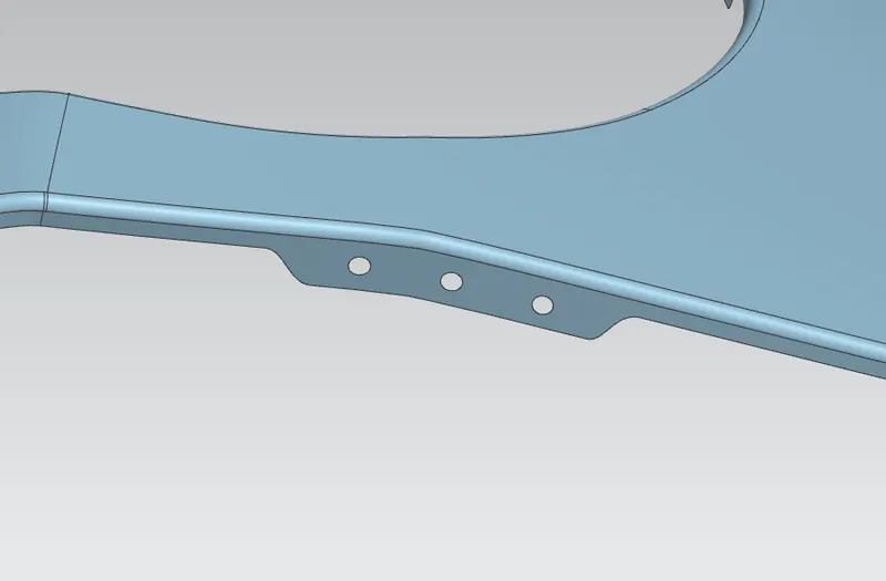
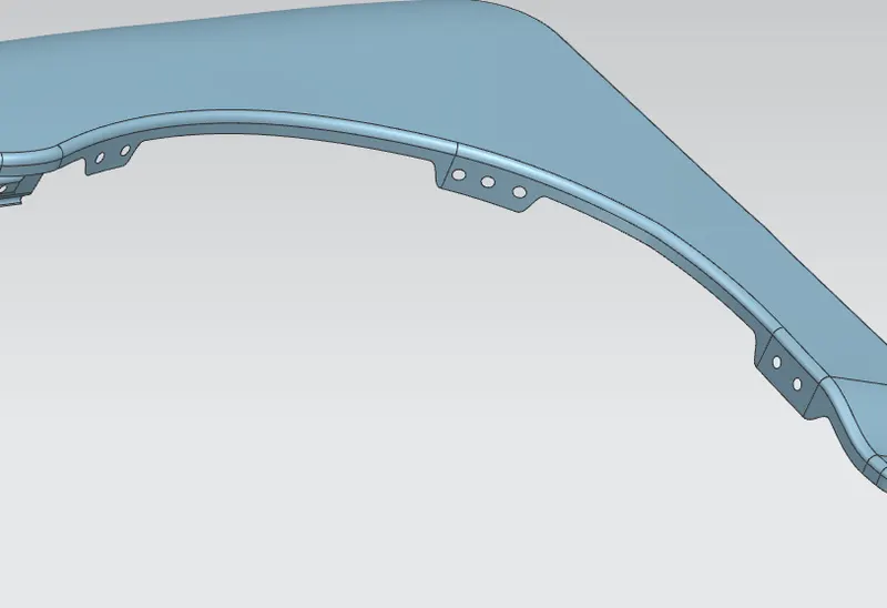
6. Baffle mounting:
It is an important mounting for a safety requirement to the pedestrian as well as engine compartment from the chipping.
MANUFACTURING PROCESS OF FENDER
The manufacturing process includes the following steps
- Firstly, unfolding and shearing are carried out on a plate, wherein a proper cold roll specification is selected at first, a cold roll is unfolded, and then the unfolded cold roll is sheared to an iron plate of the corresponding size according to production material specifications.

- Secondly, oil pressing and punching are carried out, wherein the iron plate is extended at first, then side shearing and punching are conducted on the iron plate, folding and shaping are carried out on the iron plate, and finally reshaping is carried out on the iron plate.
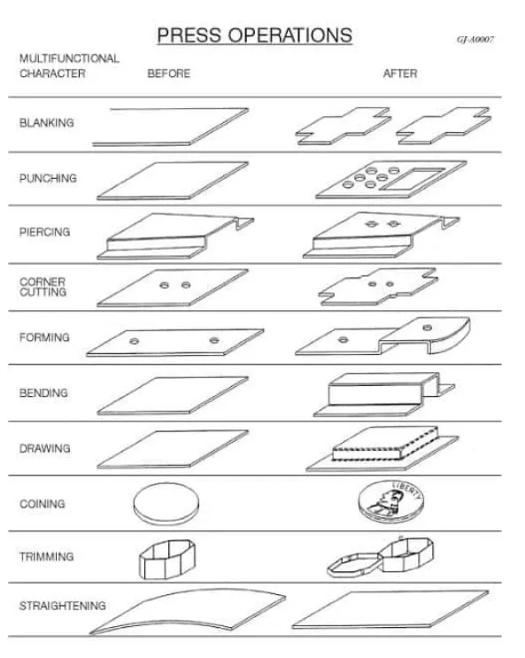
- Different type of operation:-
- Shearing Operations
- Blanking Operations
- Punching Operations
- Piercing Operations
- Trimming Operations
- Drawing Operations
- Embossing Operations
- Bending Operations
- Squeezing Operations
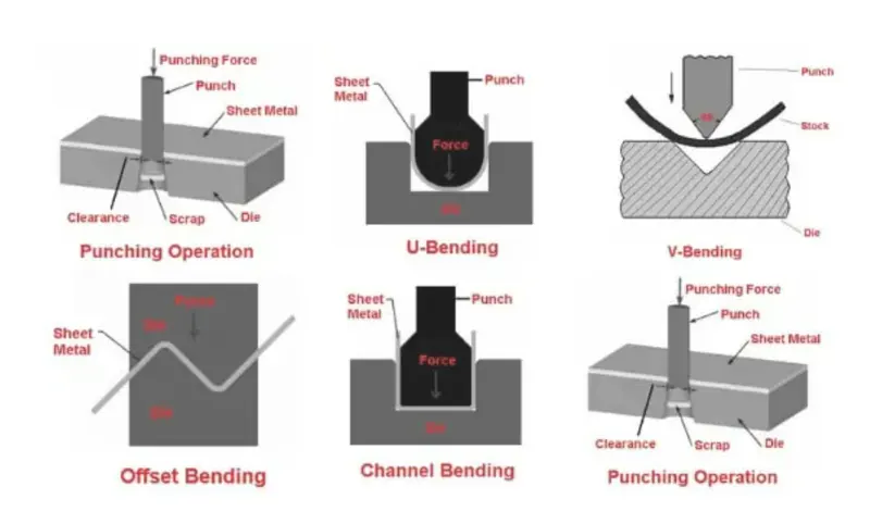
- Thirdly, small first parts of the fender are machined, first of all, the iron plate is punched to a needed outer contour blank, then the iron plate completing the outer contour blank is further shaped, and the iron plate is punched at last.
- Fourthly, installation and welding of a metal plate are conducted.
- (Embossing, Bending, Cutting and Blanking)
Rise of injection molded fender
Energy efficiency is an essential consideration in sustainable manufacturing. Injection molded fenders offer better energy efficiency, high manufacturability and offer a high-quality product at a same time. Injection molding includes 4 stages viz., filling, packing, cooling, and ejection. The defects caused during manufacturing are comparatively less. As a result, the OEMs are installing injection molded fenders in vehicles.
Material used in fender design
You can find modern fenders made from steel, aluminium, thermoplastic, and fiberglass. Steel is the most rigid and abrasion-resistant material used in making fenders. They offer the best protection from large debris and are less likely to dent. Aluminum offers the strength of metal without the heaviness of steel.
BASIC DESIGN CONSIDERATION :-
- Embossed are provided to increase the strength.
- Smooth curves are designed for easy manufacturing of panel.
- Ribs are provided to drip area mount to give structural support and extra strength.
- Maintain extra 10mm from the flat surface for the fastener holes.
- All fillets should maintain 3mm and more then 3mm radius in most regions.
- Thickness of fender is 0.75mm.
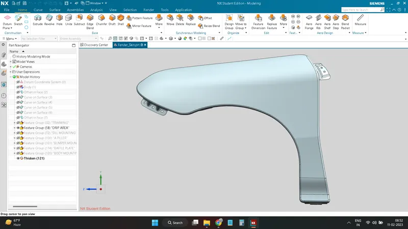
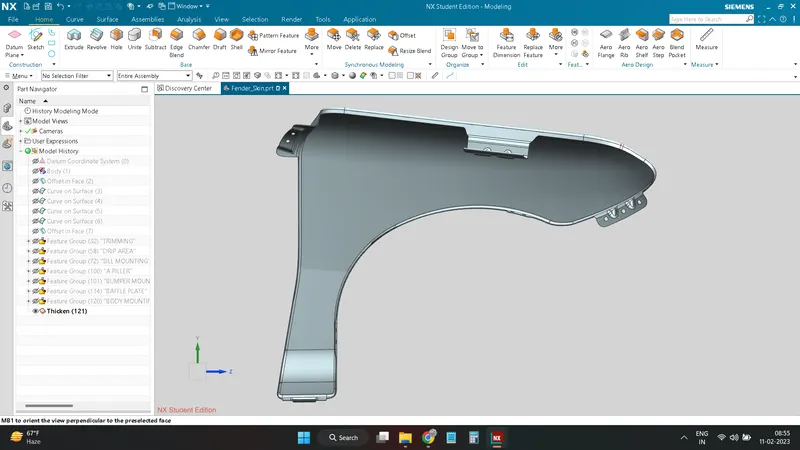
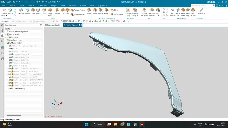
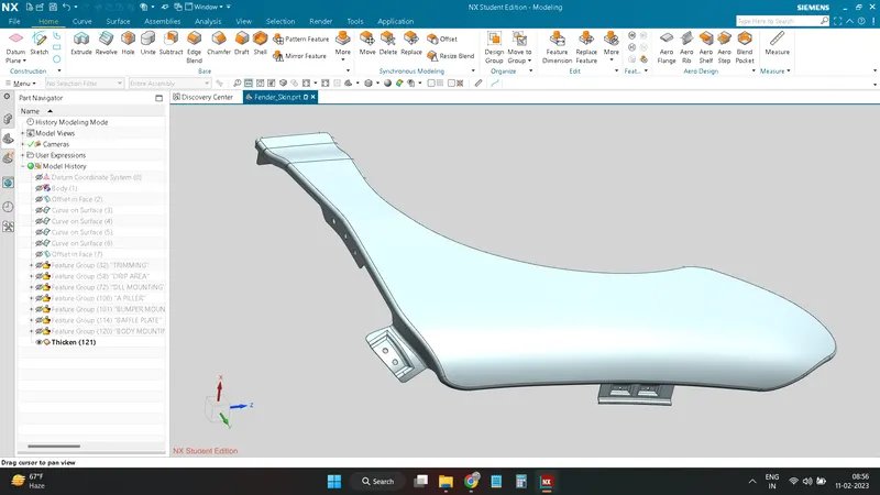
DIFFERENT VIEWS OF FENDER :-
MOUNTINGS:-
CONCLUSION
All mounting areas for the fender designed from skin data and master section is done by following all design rules.