Fender Design
Fender is a fibre/plastic component which shields the wheels and restricts mud,water,stones etc that gets carried along the rotating grooved tyre. The grooves are deliberately cut on the tyres so as to provide a smooth path for the road substances to get channelled out resulting in better traction. The substances tend to stick in these grooves for a while before getting thrown. Centrifugal force is responsible for tangential outward path taken by the flying substances from the tyre. This results in heavy bombardment of stones and other roads substances that could result in both pedestrian and the vehicle occupant to get seriously injured. To avoid the same, fender is provided both on two wheelers and four wheelers.
BIKE
A typical fender on a bike Bajaj Dominar 400 looks like this:-
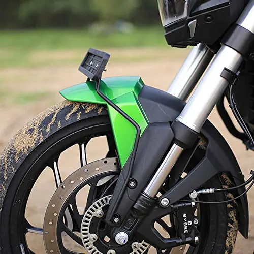
On a bike, fender is among the first part that comes in contact with the flowing air while riding. If the fender is oddly designed then it can restrict a lot of air resulting in air drag plummeting the overall performance of the bike. Along with this, fender also plays a role of channeling the air through the wheels and bike side panels for cooling purpose. The fender is designed aerodynamically to satisfy the purpose of the manufacture.
CAR
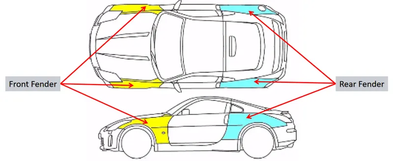
A typical fender on a car (Nissan 350Z) looks like the one shown in the pic. As it is known to us that a fender is mounted over a wheel for the fulfilment of the purpose, so a car has total 4 fenders for the 4 wheels. Two on the rear and two on the front. Mostly the rear fenders are integrated with the body while the front fenders are fitted seperately.
Fender of a car is also designed keeping both aerodynamics and safety in mind just like the one on a bike. There are 2 surfaces of a fender. The outer surface is the styling one which provides the continuity to the other smooth lines of the adjacent body parts. Fender is fitting with a total of 6 flanges that gets fastened with fasteners on the car on 6 different points which are 1) body, 2) drip 3) sill 4) cowl 5) A-pillar 6) bumper.
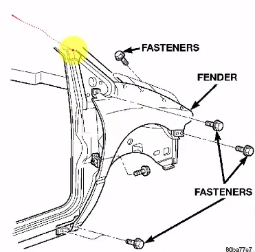
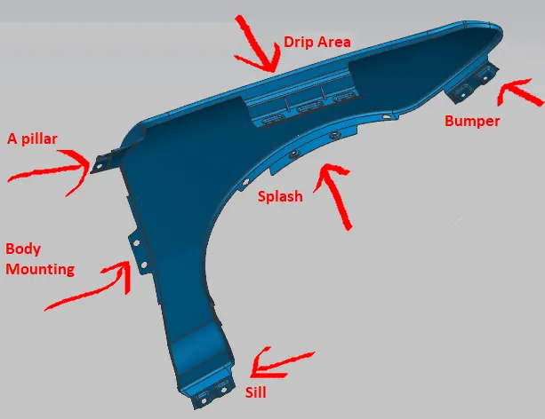
1)Body region chosen for this purpose is the region adjacent to the front doors. This is where the fender is mounted and tightened with fasteners.
*)There are two types of side fenders which are full and half fender type.
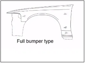
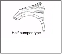
Full fender type

Full fender is one in which majority of the side area is occupied by the fender due to it's massive design. The design not only is has the basic fender but also rear view mirror mounting, headlight etc integrated to it. Because of all the other components to be assembled on the fender, the material used to create one should be strong and big in size and this is the reason why steel fenders are used in cars with full fenders. The cost of the car increases due to this. Also, a large blank is required to built one and the blank goes through a lot of wastage of the material. This also made the overall weight of the car heavy.
Half fender type

The era of half fender arrived when the designers went a step ahead in creating the masterclass. The cars with so many curved surfaces and sharp looking design needed to look more of a continous design. To bring such a design to life, the fender size was shortened and the components like headlights etc were assembled seperately and not on the fender. This opened the window for lighter material to be use and little compromise could be made in choosing a lighter yet strong enough material like fibre. With just the blank of the same size, two half fenders could be produced making it a economical part. This solved all the issues which were there in a full fender type and plummeted the performance up.
Fender design in NX-12
The skin data was already provided with a master section that helped me to create the mounting flanges.
*) The process began with trimming the side section of the sheet to 5mm. Only some regions which would be used to create the mounting flanges were left untrimmed.

1)A-pillar mounting
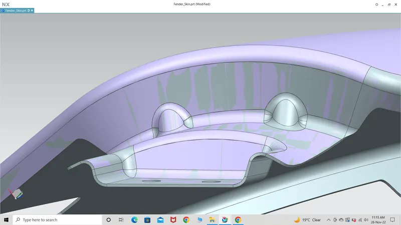
The first flange was created using curve on surface with G1 curve nature. A datum plane near to the flange was created and the sketch containing the exact shape of the mounting was created and with the help of embossing and trim sheet, A-pillar mounting flange was created. Here, the hole was created maintaining the distance of 5mm with the surroundings and 6-8mm between any two surfaces. This section was completed by giving some strength. 2 darts are created on the edge which will support the corner that connects the two surfaces by the random forces when the car would be in motion having this fender fit to it. The edges if left sharp would rub against the adjacent surfaces and they would destroy itself so smooth and curve surface is created and the darts are giving blends. The A-pillar mounting flange is completed. This mounting was the most difficult to create amongst all due to the high degree curved surface which made it tough to project the exact sketch to the face and also the emboss option.
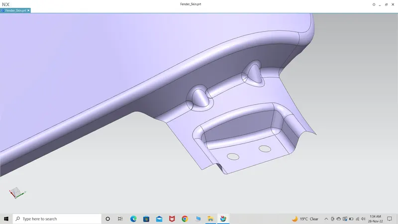
2)Drip area mounting flange
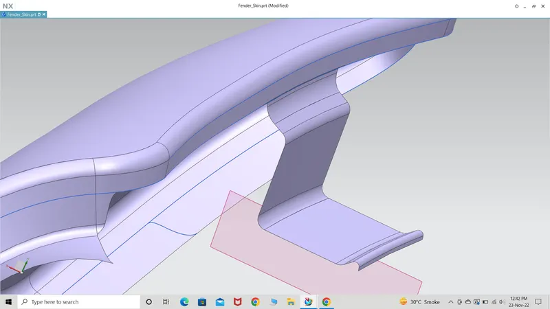
This is the only section which has to be designed according the master section. The first surface has to be 3 degree inclined, so the particular section was trimmed as it was fixed to 0 degree. A new surface which was 3 degree inclined was created and then the whole flange was created by following the same procedure as was done earlier. The end cap which is set to datum plane which is 3.75mm giving the emboss a flat surface on the other side of the mounting flange. The surface should be flat only then the fasteners would fit to the surface properly. To check whether the bottom surface is flat or curved, the analysis tool is used and radius of curvature if displayed with a value means that the surface is curved and flat if it shows infinity.
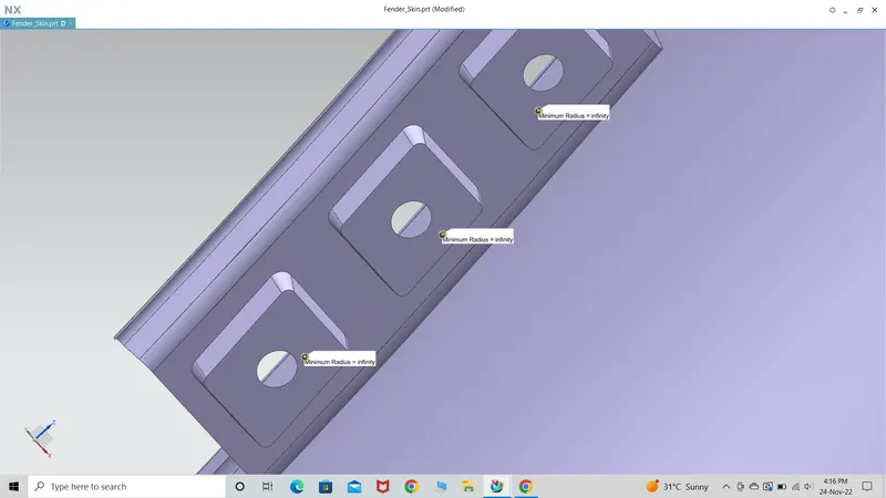
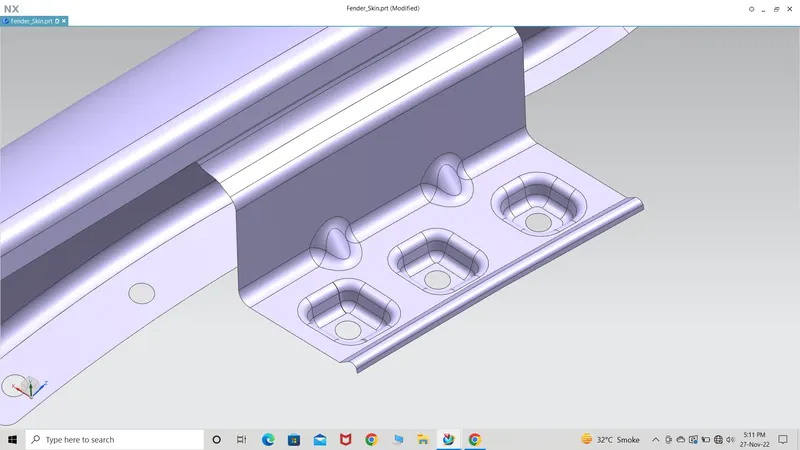
Here the distance between the fastener holes and the surrounding which must be 5mm and the space between any two surfaces must be 6-8mm rule lacked in this section. This is because with the measurements that the master section contained didn't allow enough space to follow the aforementioned measurement rules. The drip region mounting flange is completed.
3)Wheel arch or splash area mounting flange
To create this region, first it was important to recreate a small surface which has an undesirable finish. The surface was trimmed and recreated with the help of bridge curves and through curves meshing options.
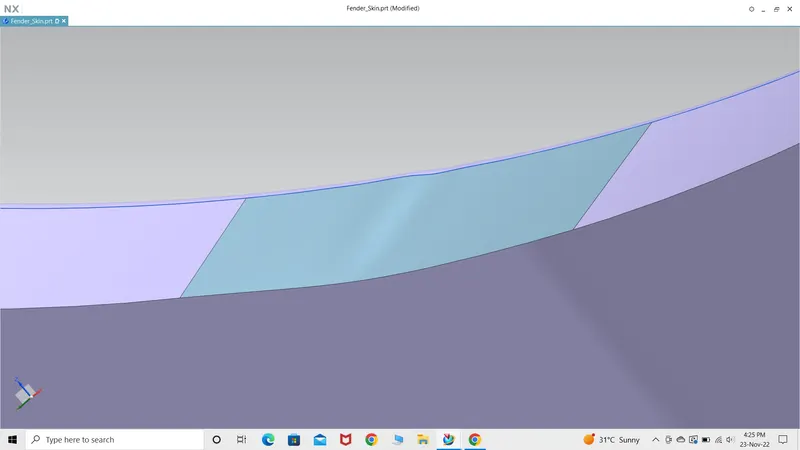
The flanges were created and here there was no need to go for embossing because these mountings won't have those fasteners used in other regions. The reason is that the baffle which is going to be fitted over here is a plastic or rubbery panel and is only used to take the hits of the objects thrown by the rotating wheel like sand particles,stone,water etc. 3 flanges were created to give a strong fitting for the baffle on the fender.
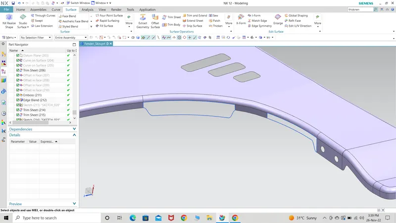
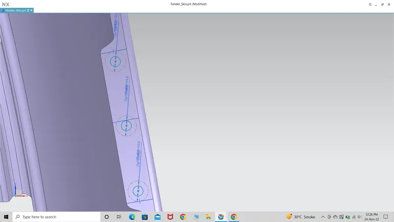
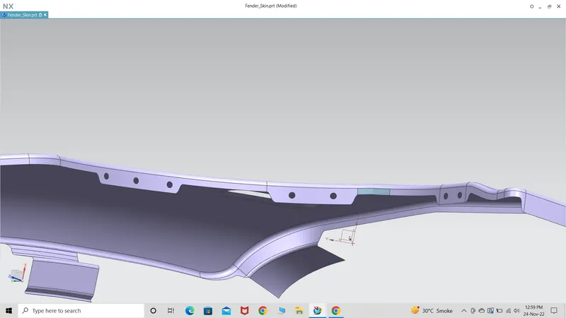
The process to create the mountings was same as mentioned earlier. It was always kept in mind that there should be no surface with sharp ends so corner reliefs were given where necessay. Wheel arch mountings is completed.
4)Sill area mounting flange
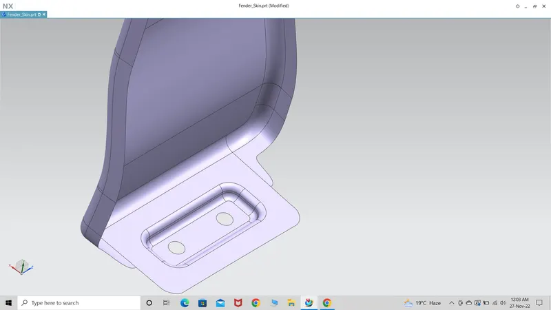
The procedure followed to create this flange was similar as mentioned earlier. Sill area mounting flange is completed.
5)Bumper mounting flange
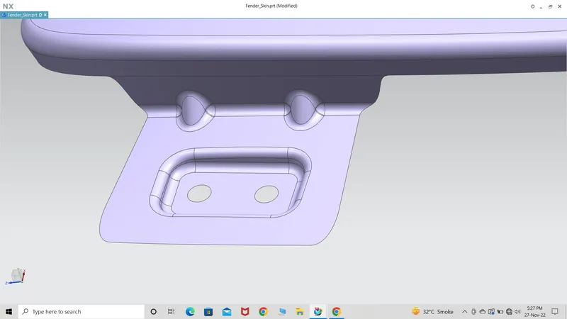
The same procedure was followed to create this surface. This region was having some very unpleasant looking edge surface so the edges were created again and trimmed the unwanted region to obtain the same region as shown above. Bumper mounting flange is completed.
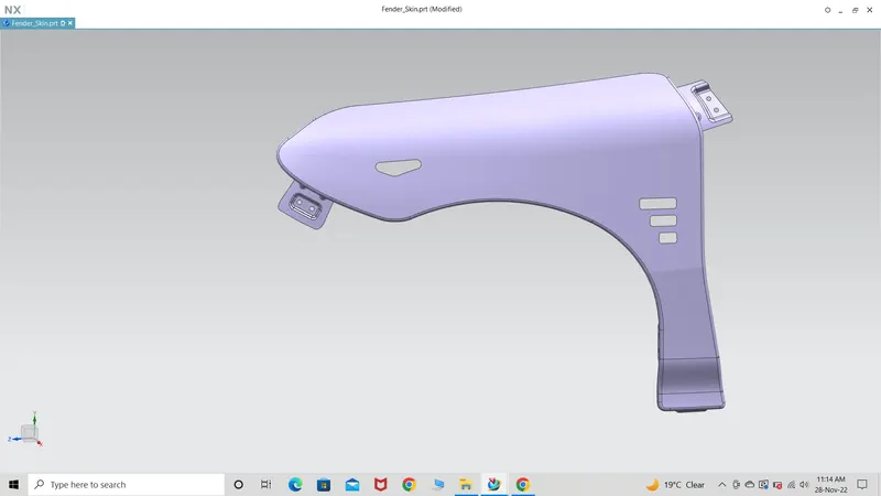
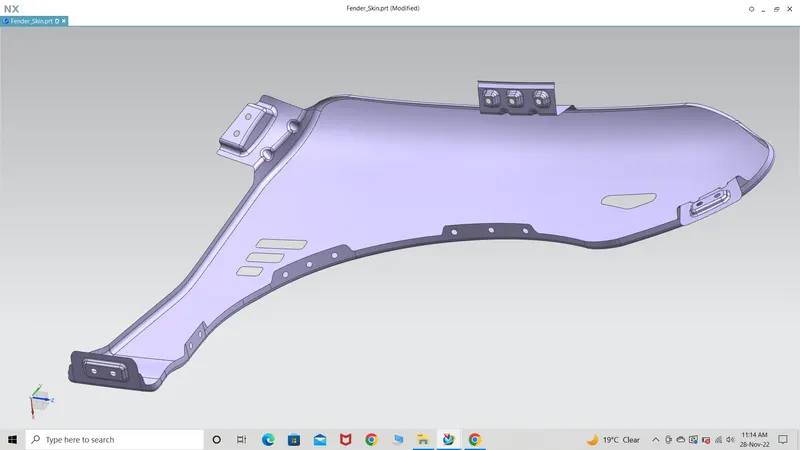
All the 5 mounting flanges were created successfully. The next part was to give the surface a thickness of 0.75mm towards inside. After trying the thickness tool, the following error got displayed.
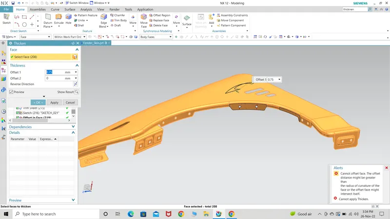
The following surfaces marked with red borders. The error was due to the curved surface that was created later and might not have been created properly.
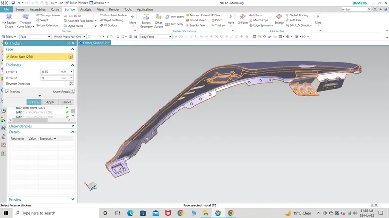
The region of concern was solved by recreating the surfaces. It was observed that by changing the color, the changes made on any region is easily visible. This made it easy to catch any irregularities or error on any of the surfaces. After thicknening the surface, there were some region with sharp edges and were given a smooth surface by blending the region.
The color of the surface had some mixture of other color which meant that there two surfaces joined with each other. One is the parent body on which the whole creation was done and the other is the surface which was thickened. Former body is hid and the remaining visible region is the final product develped and ready to move on to the next panel development process.
*) Fender is provided with two cut-outs on the face.
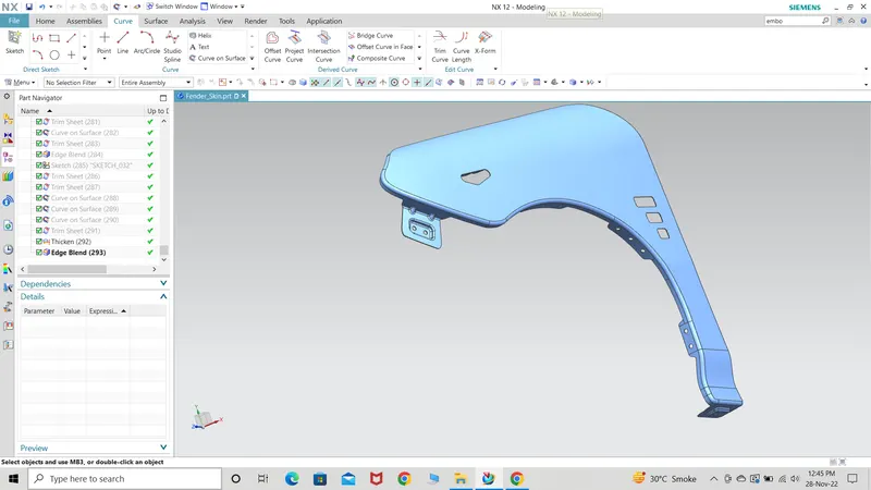
1) Indicator or side signal cut out where the indicator would be assembled on the inside region of the fender.
2) The next cut-out is a set of 3 rectangular shaped region. The reason behind it is for better performance. When the wheel is rotating, the air that enters the wheel arch region through the splitter on the face of the bumper gets trapped. The rotating wheels create turbulence which affects the aerodynamic performance of the car. So a set of cut-outs(shape depends on the car design) is provided also known as exit ducts which channel the air turmoiling inside the wheel arch region and dissipate out of the mentioned region. A smoother flow of air means less resistance to the vehicle. When both the side are given these exit ducts then a visible performance upgrade is observed.
Result
The fender is designed and checked using the master section.