Fender Design
Aim:
To design a front fender with the given skin data, master section guide and the design for manufacturing considerations.
Design Considerations:
In order to manufacture the fender [a Sheet metal] easily without any difficulties some design considerations are needed to be followed.
- 6 to 8 mm flat Surface in the mounting areas/regions.
- 3 to 5 mm hole Size for mounting points.
- No sharp corners.
- Fillets of value with a minimum of 3mm + thickness of the sheet metal.
- Reliefs at abrupt corners to reduce stress concentration.
- Flat embosses to all mounting points to increase the sheet strength locally.
- Draft angles to all embosses to ensure manufacturability.
- Ribs and darts to long and broad mounting regions to reduce vibrations, spring back and increase the structural rigidity of that region.
Design Approach:
To complete a Successful design of the fender, the following areas should be designed with the given skin data.
- Drip Area
The mounting which holds the fender with the engine compartment under the hood. The most crucial mounting area of a fender.
- A - Pillar [or] Body Mount Area
The mounting which holds the fender with the A-pillar, the first vertically inclined section of the vehicle that has the windshield in place (or) the side of the vehicle's main body that holds the door hinges.
- Bumper Mount Area
The mounting area which holds the bumper, the frontmost part of the vehicle that gives the very first impression to the customer about the beautiful look and the fender.
- Sill Mount Area
The mounting area which holds the fender with the sill, the part where the floor is present with the entering way/side and the footwell of the cabin. The lowermost region of the vehicle's upper body.
- Baffle or Wheel Well Mount Area
The mounting area which holds the baffle, the part that covers the engine compartment from the underside body till the Fender and prevents exposing the engine and the other components to the outside and also protects them against dirt, stones, water, mud and sand that gets picked up by the tyre while the vehicle is in motion.
Tools used:
- 2D Sketching Tools
- 3D Sketching Tools
- Curve On Surface
- Offset Curve in Face
- Bridge Curve
- Project Curve
- Intersection Curve
- Surface Modelling Tools
- Law Extension
- Extend Sheet
- Dart
- Trim Sheet
- Emboss
- Face Blend
- Edge Blend
- Sew
- Thicken
Skin Data:
The skin surface data is received from the styling team.
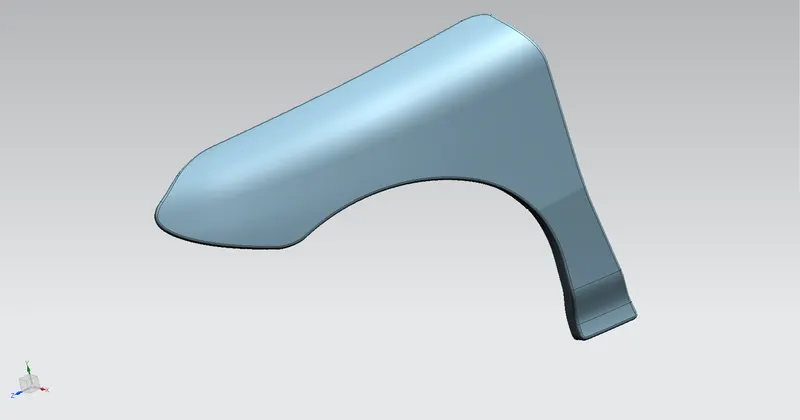
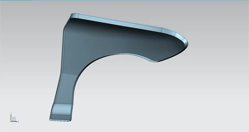
Drip Area:
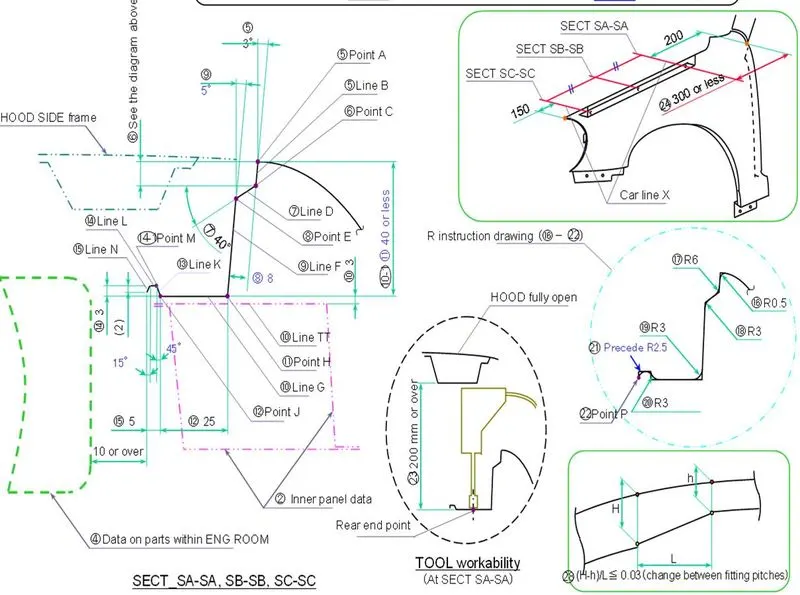
To design the Drip Area, the master section is to be followed.
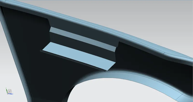
- At first, the length of the drip area is to be determined.
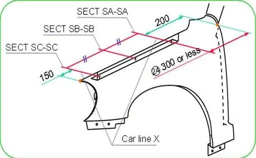
The starting point of the A-Pillar is need to be determined and the start of the section be at 300 mm or less. This 300 mm space in the drip mount will house the cowl region, wiper and wiper motor and other miscellaneous parts/components in place. And then at 150 mm distance from the foremost point the section should end. This 150 mm space in the front will help to hold the headlight assembly in place.
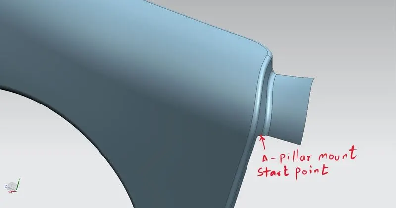
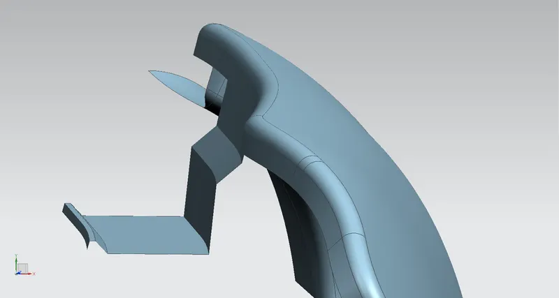
- After the drip length is determined the sheet/surface is trimmed off about the section and get the sectioned part as a resultant sheet/surface. And the created section is extended by following the master section.
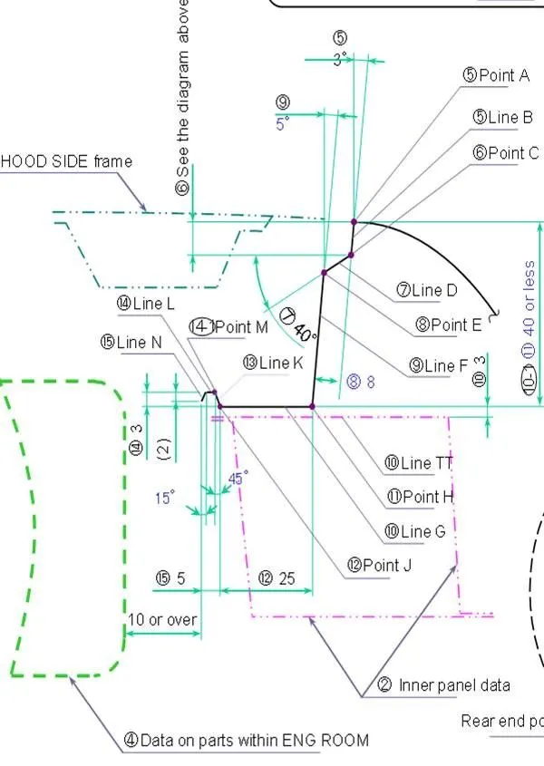
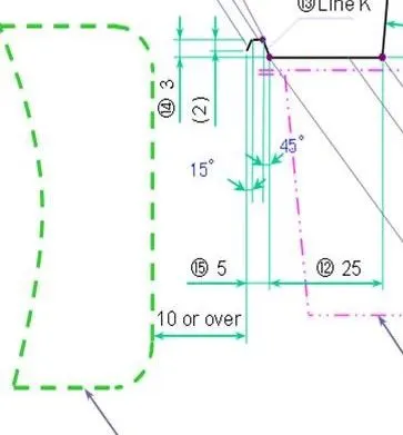
- The sheet body is extended and manipulated according to the given master section with the dimensions specified. In the final end of the section, calculate the length of the sheet with the given overall lengths, depths and the angles.
For the calculation treat the section as a right-angled triangle,
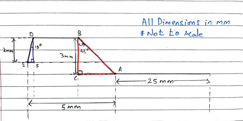
From figure, BC=3 mm & DF=2 mm.
From `triangle` ABC,
Taking tan θ,
`tan 45°=(AC)/(BC)`
`1= (AC)/3`
`AC=3 mm`
Taking sin θ,
`sin 45°=(AC)/(AB)`
`0.707= 3/(AB)`
`AB=4.24 mm`
From `triangle` DEF,
Taking tan θ,
`tan 15°=(EF)/(DF)`
`0.268= (EF)/2`
`EF=0.536 mm`
Taking sin θ,
`sin 15°=(EF)/(DE)`
`0.259= 0.536/(DE)`
`DE=2.07 mm`
From figure,
WKT,
`AE=5 mm`
`AE=AC+CF+FE`
`AE=3+CF+0.536`
`CF=1.464 mm`
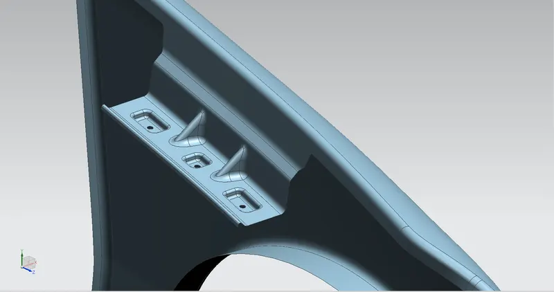
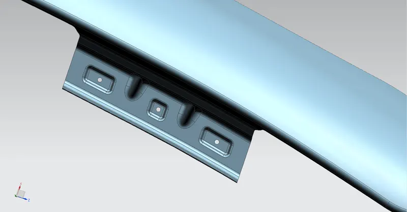
- Fillets/Blends are added to smoothen the surface.
- Darts are added to reduce the spring back in the material.
- Embosses with draft angles and holes are created and face/edge blends are also given to give a smooth look to the surface.
A-Pilar Mount Area:
Next step is to create the A-Pillar Mounting Area. The mounting embosses and the holes are created by following the basics of design for manufacture techniques to ensure the manufacturability of the part.
Blends are provided to give a good smoother looking surface.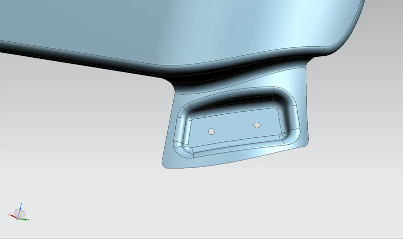
Bumper, Baffle and Sill Mounting Areas:
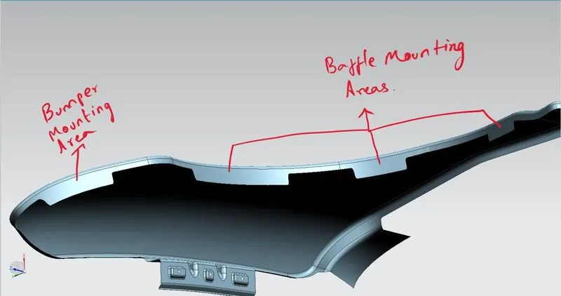
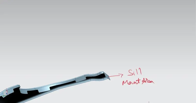
For bumper, baffle and sill mounting points, the sheet is trimmed from the front side till the sill area by creating the spaces for the mounts.
Bumper Mount Area:
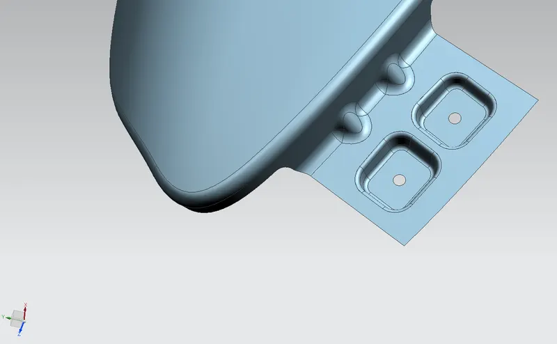
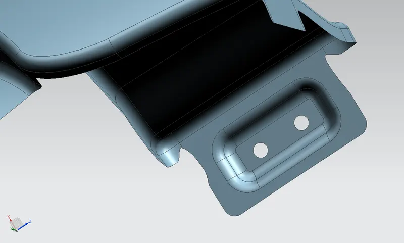
The bumper mounting created by extending the sheet for the purpose of adding the emboss and the holes. Darts are added to reduce the spring back criteria and the vibrations. The design for manufacturability basis is followed and extra sheet material, if any, is trimmed off to reduce wastage of resources.
Sill Mount Area:
The sill mounting is created by extending the sheet and adding the emboss and holes. Reliefs are given in the abrupt corners to reduce stress concentration.
Baffle Mount Area:
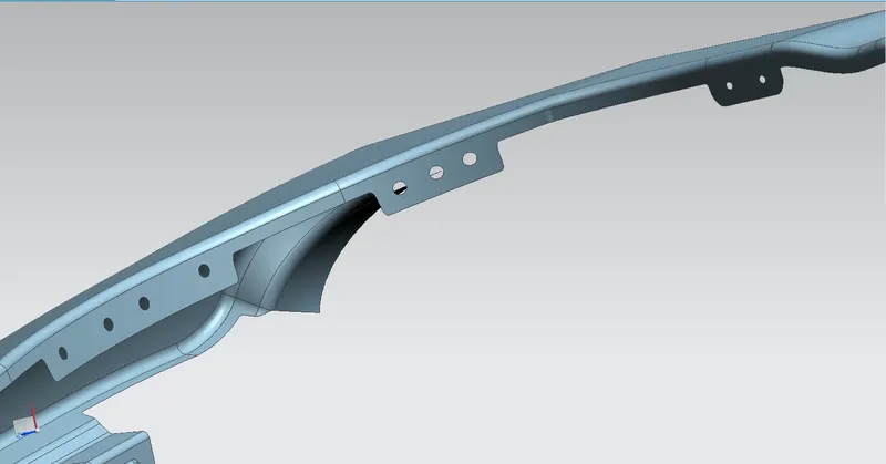
The baffle or wheel well mount area is created by adding holes to the regions of the mounting points. The design for manufacturability basis is followed.
Final features and Thicken:
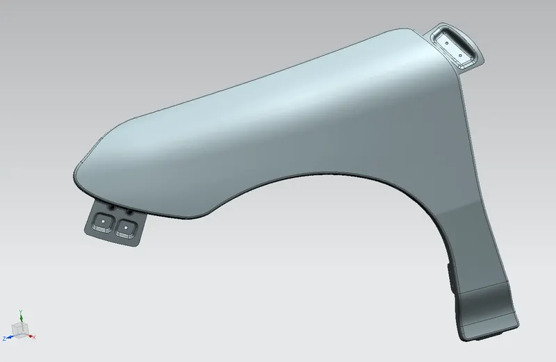
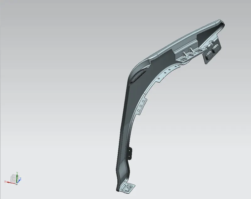
Finally, when the entire design is completed all the features are checked for correctness and the sharp corner are trimmed off to give smooth curvature and easy manufacturability.
Then, the surface is thickened by 0.75 mm inwards from the skin to complete the model.
Since fender is a sheet metal component, it is manufactured by sheet metal working operations.
Sheet Metal Operations
The common types of sheet metal operations are shearing, blanking, punching, piercing, trimming, drawing, embossing, bending, and squeezing operations.
Shearing Operations
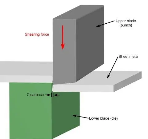
The Shearing operation is a cut in a straight line across a strip, sheet, or bar. It leaves a lean edge on the piece of metal that is sheared or cut. In this operation, a sheet metal workpiece is placed or kept between two dies from one end. And, the punch is hit at the other end of the sheet, producing a shearing effect. This type of sheet metal operation has three basic stages:
- Plastic deformation occurs when a metal is sandwiched between the upper and lower blades of shear when pressure is applied. It penetrates the metal for around 5 to 40% of its thickness.
- A fracture occurs at the spot where the most stress is concentrated.
- Shear – The metal is sheared once small fractures are discovered.
Blanking Operations
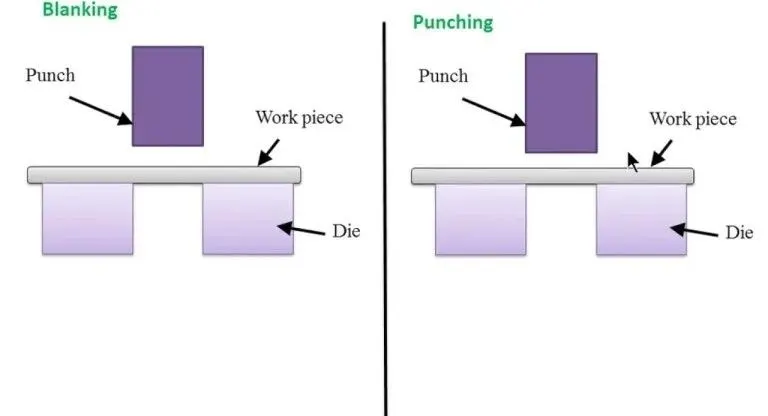
It is the process of cutting a complete piece of sheet metal. In which there is ample junk all around, as shown in fig. For this type of sheet metal operation, a punch and die are used.
Punching Operations
A punch and die technique is used to create circular holes in a sheet of metal. Although this is the polar opposite of blanking, the process is essentially identical. Blanking processes, for example, require the employment of a punch and die.
Piercing Operations
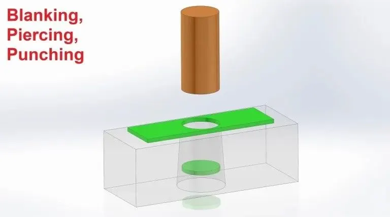
As indicated in the figure, piercing is the process of creating desired shape holes in a piece of sheet metal without taking any material from the sheet or removing a very little quantity of material. In this operation, both punch and die are used. Bullet-shaped punches are commonly employed in piercing operations.
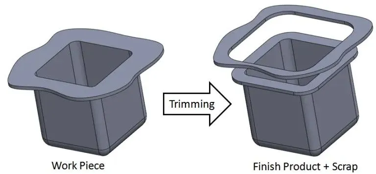
Trimming Operations
The shaving operation is another name for trimming. It is a finishing technique that involves removing burrs from cut edges in order to smooth them down and improve dimensional accuracy.
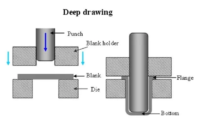
Drawing Operations
It is the process of fabricating thin-walled hollows or vessel-shaped pieces out of sheet metal. It can be classified into two groups:
Deep drawing – the object to be drawn has a depth that is greater than its breadth.
Shallow drawing – the item to be drawn has a length that is less than its width. Pans, tubes, and cams are instances of drawing.
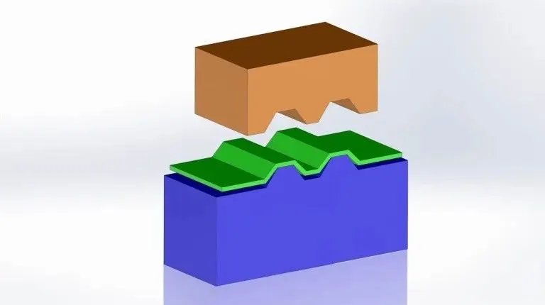
Embossing Operations
It’s a metalworking technique for creating raised surfaces or letters in sheet metal. During this operation, the thickness of the metal does not change.
Bending Operations
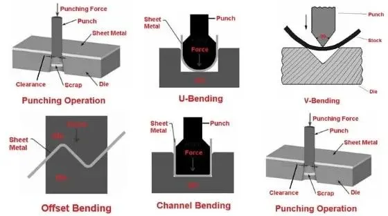
When forces are applied to certain regions, this happens. With the inner surface under compression and the outer surface in tension, the metal flow is uniform along the bend axis. The following are the various types of sheet metal bending operations:
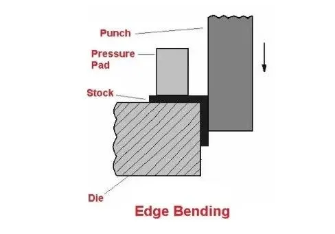
Edge bending
As indicated in the diagram, it is a type of bending operation in which a piece of sheet metal is fixed or held between two dies from one end. The other end is thus compelled to strike the free or unfixed punch. To complete the shaping process, the sheet metal piece’s free or unfixed edge is bent.
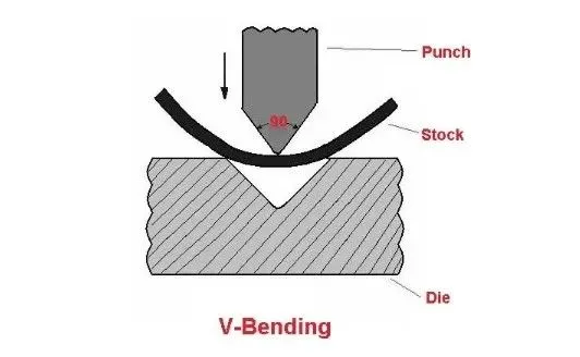
V-bending
When a piece of sheet metal is squeezed between the die and the punch in this type of bending operation, it is shaped into a V-shape in the die.
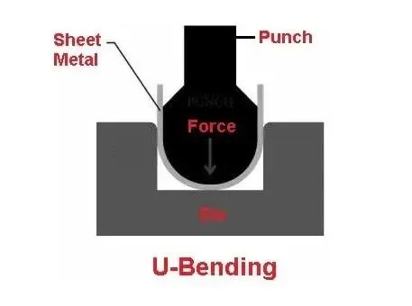
U-bending
The sheet metal component is shaped into a U-shape in this type of bending operation, in which the punch is forced into the die by a force.
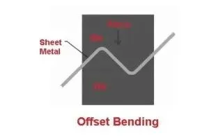
Offset bending
It is a type of bending operation in which a piece of sheet metal is punched and die-formed into an offset shape.
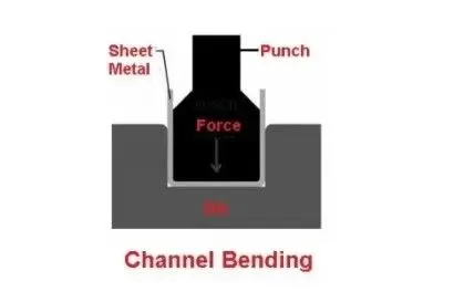
Channel bending
When a force is applied to the punch to advance it into the die, the sheet metal piece in between the punch and die takes on the shape of the die and punch, i.e. a channel shape.
Squeezing Operations
It is a simple and common method of producing ductile metals. It can perform a variety of tasks, including sizing, coining, and riveting.
Sizing – the sizing technique decreases the thickness of the metal by squeezing it. Only the surface where the die and the workpiece come into contact is sized in an open die.
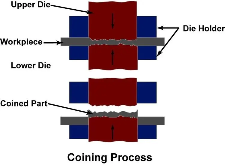
Coining – It’s the process of pressing metal into a die and allowing it to flow into the die space. Medals, coins, and jewelry, for example.
Conclusion:
Hence, the front fender is modelled with the given skin data and with the help of drip area master section and the design for manufacturability criteria is followed and the manufacturing process is listed and described.