Fender Design
Aim:
To design the fender by using the given master section for Trip area, Sill, Bumper, Baffle and A-Pillar mount according to the engineering standards.
Theory:
Fender:
Fender is the part of an automobile, motor cycle or other vehicle body that frames a wheel well (the fender underside). Its parimary purpose is to prevent sand, mud, rocks, liquids and other road spray from being thrown into the air by the rotating tire. Fenders are typically rigid and can be damaged by contact with the road surface. The Fender image is shown below
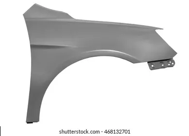

Sticky materials such as mud may adhere to the smooth outer tire surface, while smooth loose objects such as stones can become temporarily embedded in the tread grooves as the tire rolls over the ground. These materials can be ejected from the surface of the tire at high velocity as the tire imparts kinetic energy to the attached objects. For a vehicle moving forward, the top of the tire is rotating upward and forward, and can throw objects into the air at other vehicles or pedestrains in front of the vehicle.
Types of Fender:
There are mainly two types of fenders :
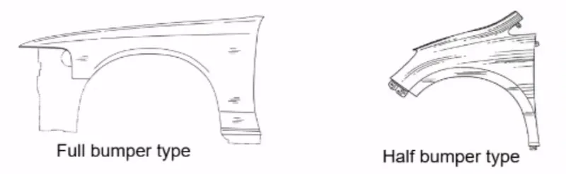
1. Full Bumper Type:
The full bumper type fender was used in old cars, it covers the full area until the front lighting. But it has a lot of sheet metal material which is unnecessary and increases the weight of the fender. These type fenders are no longer used in the automobiles.
2. Half Bumper Type:
This half bumper type is used for mainly cost and material cutting purpose as this type is also provides ease of manufacturing and the strength is also improved for half bumper type fender.
MANUFACTURING PROCESS IN METAL FORMING:
- One of the most important things about metal is that it can undergo plastic deformation. That doesn't mean metal is made out of plastic, but it can do one of the things that plastics can: It literally can take on almost any shape that we can imagine.
- The process of deformation begins with a blank, a quantity of metal in some basic form that will undergo the change in shape. The blank becomes the workpiece -- the piece of metal to be reshaped -- in the metal forming process. For automotive metal forming, the blank is often made of sheet metal, which can be stamped, cut or bent into a shape needed for an automobile's body.
Here are some ways that a metal workpiece can be deformed during the automotive manufacturing process:
Bending:
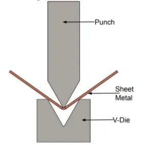
- In bending, force is applied to a sheet metal workpiece to produce a curvature of the surface. Bending is generally used to produce simple curved surfaces rather than complex ones.
- A mechanically operated press drives a punch against sheet metal, forcing it into a simple die with enough pressure to produce a permanent change in the metal's shape.
- The amount of pressure is important. If not enough pressure is applied, the metal can simply spring back into its original shape. If too much is applied, it can break.
Drawing:
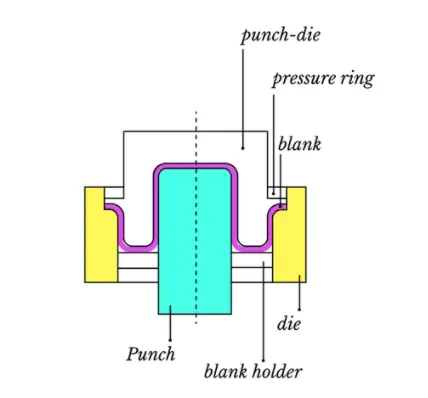
- In drawing, the sheet metal is forced against a die that has been cut into the three-dimensional, often curved shape that the sheet metal is to take on. In effect, the die is used as a mold for the metal.
- This technique can produce relatively complex shapes. Once again, pressure is applied to the workpiece using a hydraulically or mechanically operated punch. There are a number of dangers involved, not so much to people (since the process is largely mechanized) but to the metal itself.
- It can crack from too much pressure or wrinkle from its interaction with the die. Lubricant can be used to make the metal slide more smoothly against the die, avoiding the possibility of wrinkling.
- Alternatively, the wrinkled edges can be trimmed from the metal in a separate operation. This method is commonly used to make auto body parts and fuel tanks.
Stamping:
- In stamping, a device called a stamping press is used with a series of dies to cut and form metal into various shapes. This is commonly used to make auto parts such as hubcaps and fenders.
Extrusion:
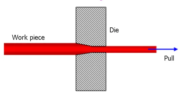
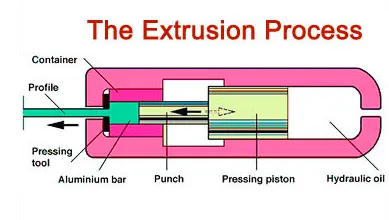
- Extrusion can be used to produce long metal objects, such as rods and tubes. The metal workpiece is forced into a die with a hole in the opposite end. The metal is extruded through the hole to form the shape. Extrusion can be used to manufacture important parts of a car's drive train or the anchors that hold seatbelts in place.
Forging:
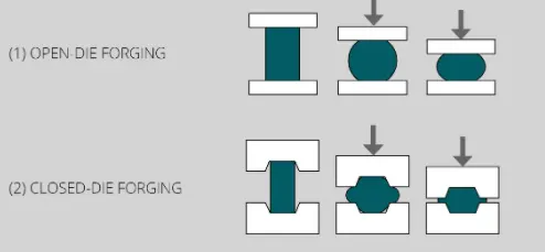
- The forging process uses a hammer or press that is essentially a mechanized version of the hammers used by ancient blacksmiths. The metal is hammered against a surface that serves as an anvil. It can be hammered repeatedly so as to form complex shapes. This can be used as an alternative to the drawing process.
Manufacturing process of car fender:
- The manufacturing process includes the following steps that firstly, unfolding and shearing are carried out on a plate, wherein a proper cold roll specification is selected at first, a cold roll is unfolded.
- Then the unfolded cold roll is sheared to an iron plate of the corresponding size according to production material specifications.
- Secondly, oil pressing and punching are carried out, wherein the iron plate is extended at first, then side shearing and punching are conducted on the iron plate, folding and shaping are carried out on the iron plate, and finally reshaping is carried out on the iron plate; thirdly, small first parts of the fender are machined, wherein first of all, the iron plate is punched to a needed outer contour blank.
- Then the iron plate completing the outer contour blank is further shaped, and the iron plate is punched at last; fourthly, installation and welding of a metal plate are conducted.
- The manufacturing process for the car fender is simple and high in production efficiency.
A body of the fender and the small parts can be separately machined, so waiting time is shortened and working efficiency of production is improved.
Design parameters:
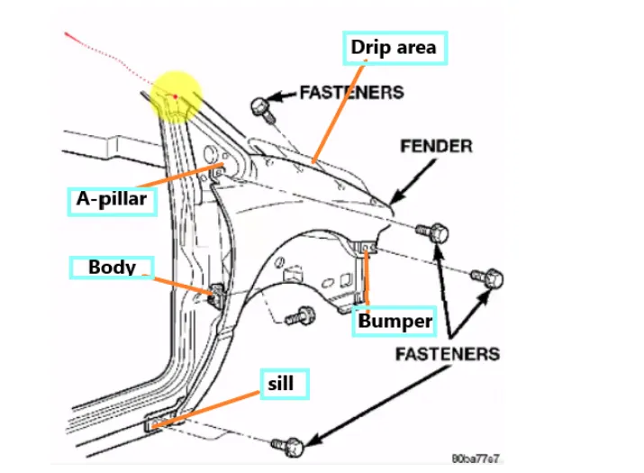
The front fender is manufactured as a separate part, this is then mounted to the body of car for this the front fender basically has 5 mounting points can differ from one OEM to another OEM. The following is the important areas.
Drip Area Mounting:
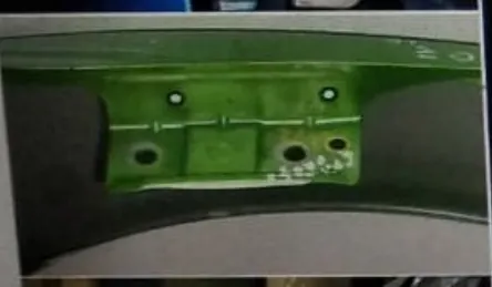
- Drip area mounting is the important part in the fender. This mounting is attached to the engine compartment of the car.
- Fender drip area is mounted via weldnuts to the engine compartment.
- A minimum of 150mm distance is kept from the front side and a distance 300mm or less can be kept on the rear side.
- The total length of drip area from the top of fender should be less than 40mm.
- This is to avoid the springback during the manufacturing.
- The edge of the mounting should atleast 10mm away from any nearby component in the engine.
- A rigidity bead is provided at the end to increase the strength of the mounting.
A-Pillar Area Mounting:
- The A-pillar area mounting depends upon the A-pillar of the car.
- The mounting can also be provided with ribs to strengthen the part.
- This mounting is critical in design as it has to be mounted on A-pillar properly.
Bumper Area Mounting:
- Another mounting point is created for the body side on the fender.
- This mounting is created such that it can be mounted on the body of the car.
- It may consist of one or two bolting holes.
Sill Area Mounting:
- Sill is the panel directly below the bottom of the door supporting the floor and may be used to combine the floor and the body .
- The bottom end of the fender is mounting on the sill body for reinforcement of the fender panel ,thus the sill mounting position is designed with holes and emboss , M5 fasteners are used to fix the fenders on the sill body .
Baffle Area Mounting:
- Sometimes fender is also provided with the cowl area mounting.
- This mounting is on the top side of the fender.
Design Procedure:
Drip Area:
Parameters:
- Drip area mounting is the important part in the fender. This mounting is attached to the engine compartment of the car.
- Fender drip area is mounted via weldnuts to the engine compartment.
- A minimum of 150mm distance is kept from the front side and a distance 300mm or less can be kept on the rear side.
- The total length of drip area from the top of fender should be less than 40mm.
- This is to avoid the springback during the manufacturing.
- The edge of the mounting should atleast 10mm away from any nearby component in the engine.
- A rigidity bead is provided at the end to increase the strength of the mounting.
Procedure:
- The skin data from given file is we need to open first in the NX cad software and in that we need to create the some mounting area for the fender.
- The fender mounting has the different types usually its vary for OEM to another OEM.
- Here we are going to create the Drip area, A-Piller, sill area, Bumper mountings and Baffle mountings area in the given skin data based on the Master section provided . The below image shows the Fender Skin and the Master Section
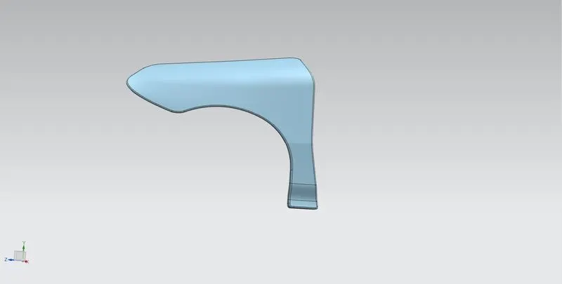
- From the skin data first we need to offset the edge curve for 5mm for trim the remaining surface for reduce the matrial. and for the required mounting places leave the area.
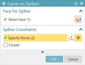
- Next step is to draw the curve on the suface by using curve on surface tool as shown in figure.
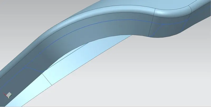
- Then the next step is to trim the unwanted surface by using the trim sheet tool as shown in figure.
- And this is repeated on some surface area of the skin data for the another mountings as well.
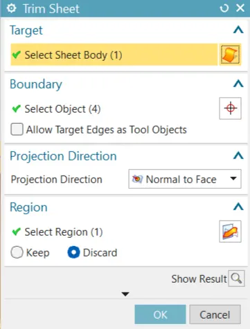
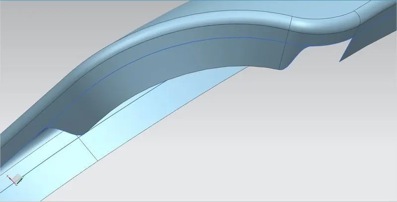
- Then the Drip area creation as shown in the master section we need some space from the A-piller to front side for 200mm and 150mm.
- And for that area next step is to create the surface over there using the law extension tool we create the surface as shown in figure.
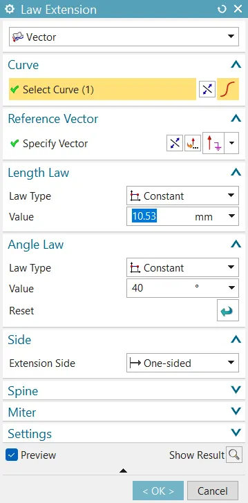
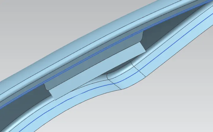
- From the given mater section data we create the remainning surfaces by same tool called law extension tool and for the lengthe and the angle we calculate from the master section drawing and this created sufaces are shown in figure.
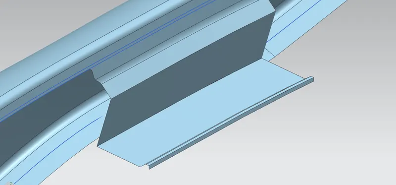
- Then we create dart to strengthen the Flange using Dart option.
- Then Blend is given to the edges as per master Section using Edge or Face Blend.
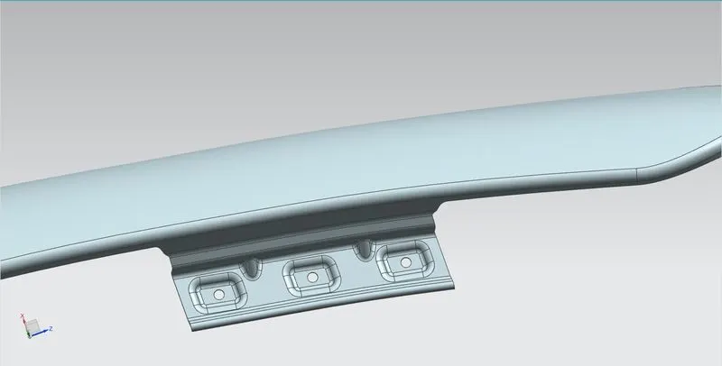
- Then next step is to create the mounting hole in that surface and for that we create the embossed surface.
- For creating the embossed surface we need a plane from that area and the new plane is created by using the three point plane option.
- In that plane we create the sketch for emboss process this sketch is drawn in the new created datum plane as shown in figure.
- After the sketch is done next step is to create the emboss usin Emboss optionthe sketch for emboss for the 3.5mm.
- Then the Blend is given to the edges to smooth the surface using Edge or Face blend option.
- Then the hole for 5mm radius is created and also some space for 10mm hole is creteated for the fastner head clearance
- Then trim the hole using Trim sheet tool option.
- Thus the Drip area Mounting has completly done. The image shows the Drip Area Mounting
A-Pillar Area:
Parameters:
- The A-pillar area mounting depends upon the A-pillar of the car.
- The mounting can also be provided with ribs to strengthen the part.
- This mounting is critical in design as it has to be mounted on A-pillar properly.
Procedure:
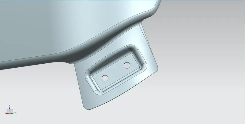
- The Drip area Mountion procedure is followed for creating the A - Pillar Area Mounting. The image shows the A - Pillar Area Mounting
Bumper Area Mounting:
Parameters:
- Another mounting point is created for the bumper side on the fender.
- This mounting is created such that it can be mounted on the bumper of the car.
- It may consist of one or two bolting holes.
Procedure:
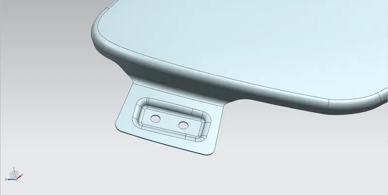
- The Drip area Mountion procedure is followed for creating the A - Pillar Area Mounting. The image shows the Bumper Area Mounting
Sill Area Mounting:
Parameter:
- Sill is the panel directly below the bottom of the door supporting the floor and may be used to combine the floor and the body .
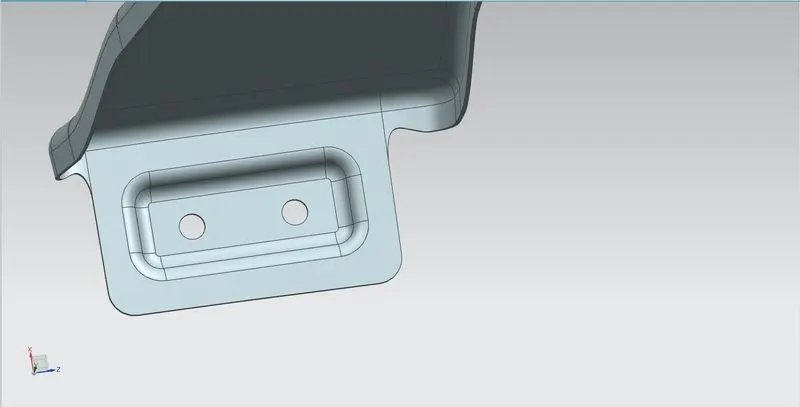
- The bottom end of the fender is mounting on the sill body for reinforcement of the fender panel ,thus the sill mounting position is designed with holes and emboss , M5 fasteners are used to fix the fenders on the sill body .
Procedure:
- The Drip area Mountion procedure is followed for creating the A - Pillar Area Mounting. The image shows the Sil Area Mounting
Baffle Area Mounting:
Parameter:
- Sometimes fender is also provided with the cowl area mounting.
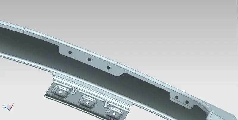
- This mounting is on the top side of the fender.
Procedure:
- The Drip area Mountion procedure is followed for creating the A - Pillar Area Mounting. The image shows the Cowl Area Mounting
- After completing all mounting areas then the thickness of 0.75mm inward on the final sewed surface of the fender to the sheet metal parameters.
- Then the sharp edges of the Mounting areas are blended using Edge blend option.
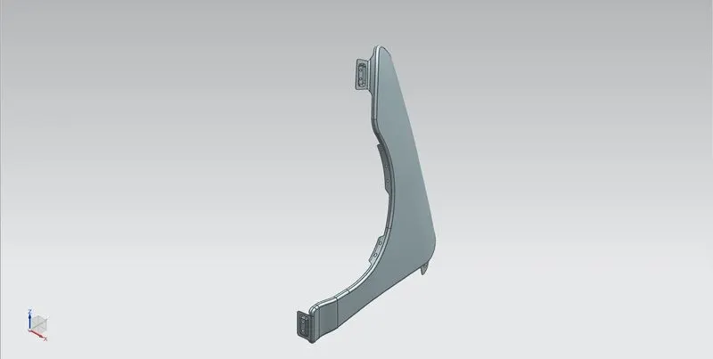
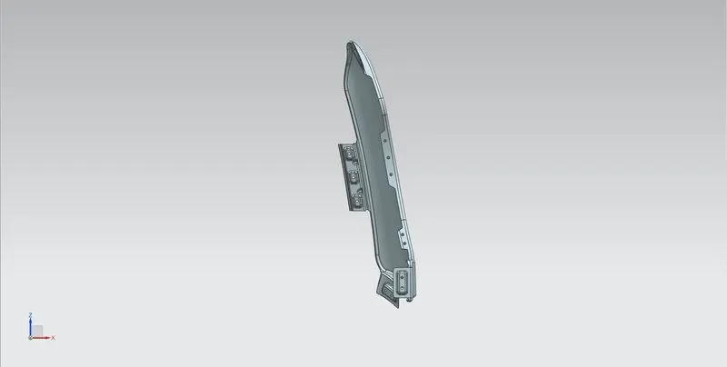
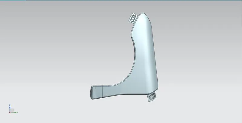
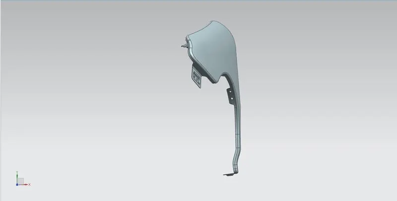
Different Views OF Fender:
Conclusion:
Hence we design the fender by using the give master section for Drip area and design the sill, Bumper, Baffle and A-Pillar mount according to the engineering standards is done sucessfully.