Energy management system (EMS)
Energy distribution flowchart:
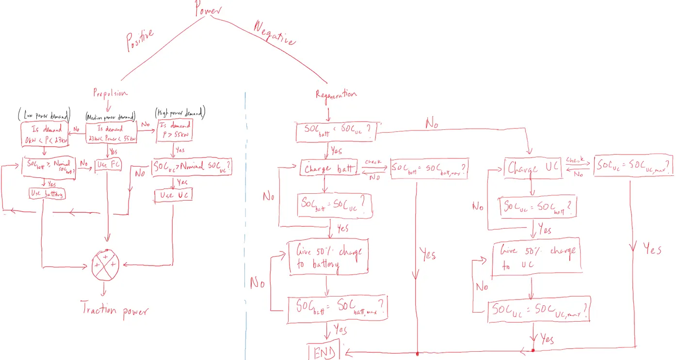
Preferred mode of operation:
- Low power demand; constant cruising speed (on a highway for instance) - use battery (power demand between 0 and 23kW)
- Medium power demand - use fuel cell (power demand between 23kW and 55kW)
- High power demand; during transient conditions - use ultracapacitor (power demand greater than 55kW)
However, nominal SOC criteria must be met for battery and ultracapacitor to go according to the above. If not, one of the three systems need to take over as backup.
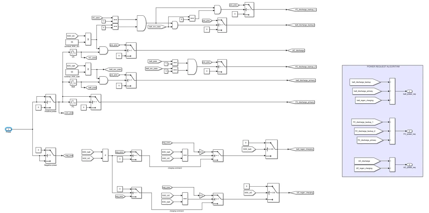
Model:
Power demand input:
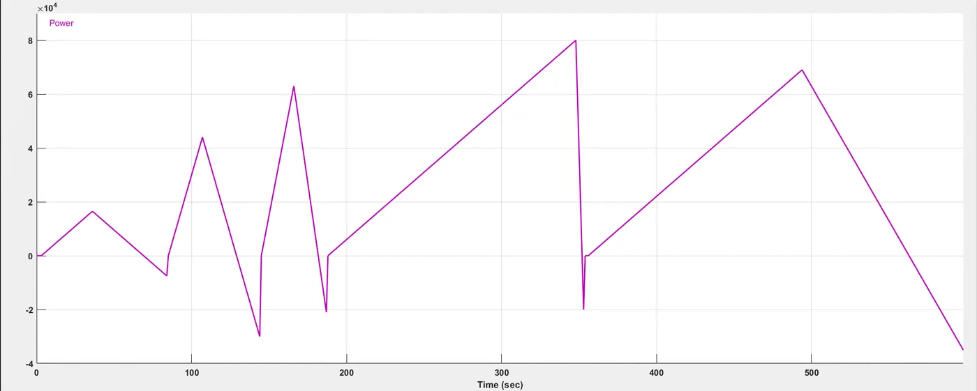
- All scenarios need to be tested with this input
Case 1: SOC_UC = SOC_batt AND SOC_UC && SOC_batt > SOC_nominal:
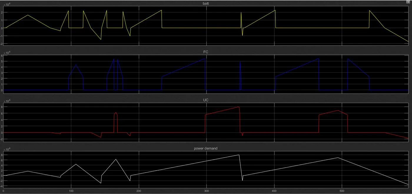
- In this case, the preferred mode of operation will continue (refer above).
- FC handles power demand that is between 23kW and 55kW
- Battery handles power demand that is between 0 and 23kW whilst also intaking negative power when power demand is negative
- UC only switches on when power demand is greater than 55kW and to intake negative power
- It is not evident but as part of the energy management algorithm, during negative power demand, if the SOC of battery and UC are equal, power is distributed equally. If zoomed in closely, every movement below 0kW for both battery and UC is shared equally whenever power demand goes below 0kW.
Case 2: SOC_UC = SOC_batt BUT SOC_UC && SOC_batt < SOC_nominal:
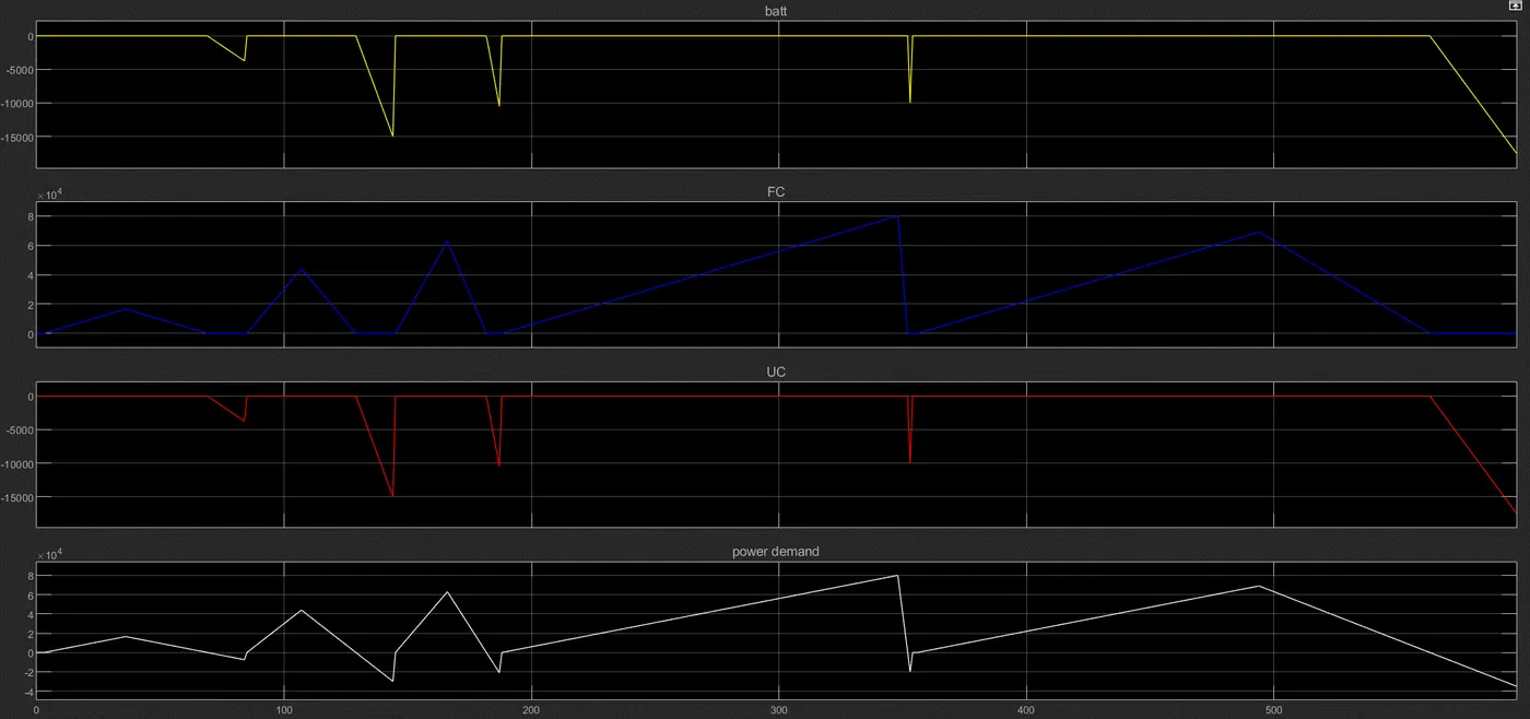
- Because the SOC of both UC and battery don't satisfy the minimum SOC criteria, they cannot be used for propulsion. Hence, the FC is seen as supplying all the power throughout the cycle, while the battery and UC share the negative power equally to increase their SOC beyond the minimum requirement.
- As is evident, the FC follows the exact path as the power demand except at the points when the power demand is negative, since FC cannot absorb any negative power.
Case 3: SOC_UC > SOC_batt AND SOC_UC && SOC_batt > SOC_nominal:
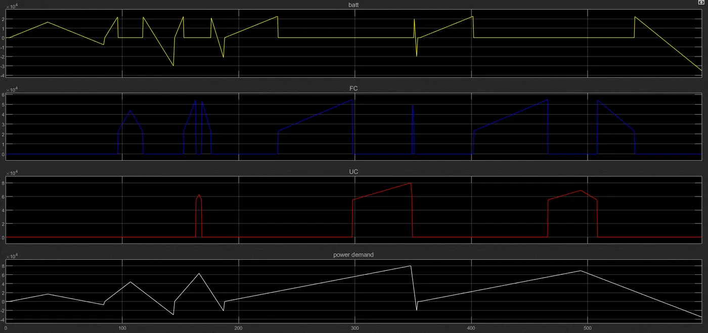
- Because the SOC of UC is greater than that of the battery, all the negative power will be given to the battery until it reaches the same SOC level that the UC has, thus the UC is seen as only a propulsion source here and not absorbing any negative power.
Case 4: SOC_UC < SOC_batt AND SOC_UC && SOC_batt > SOC_nominal:
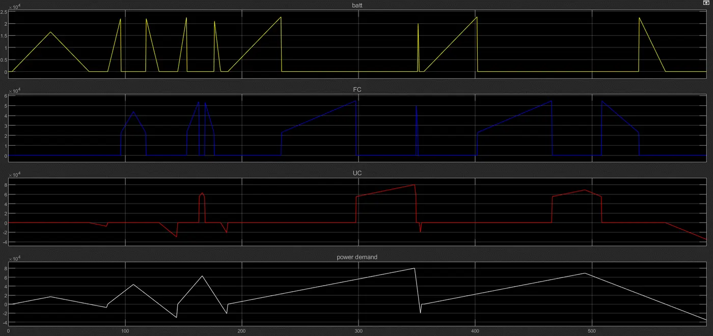
- The opposite of Case 3 happens here. All the negative power is taken by the UC until it can reach the SOC level of the battery.
Case 5: SOC_UC < SOC_batt AND SOC_batt > SOC_nominal BUT SOC_UC < SOC_nominal:
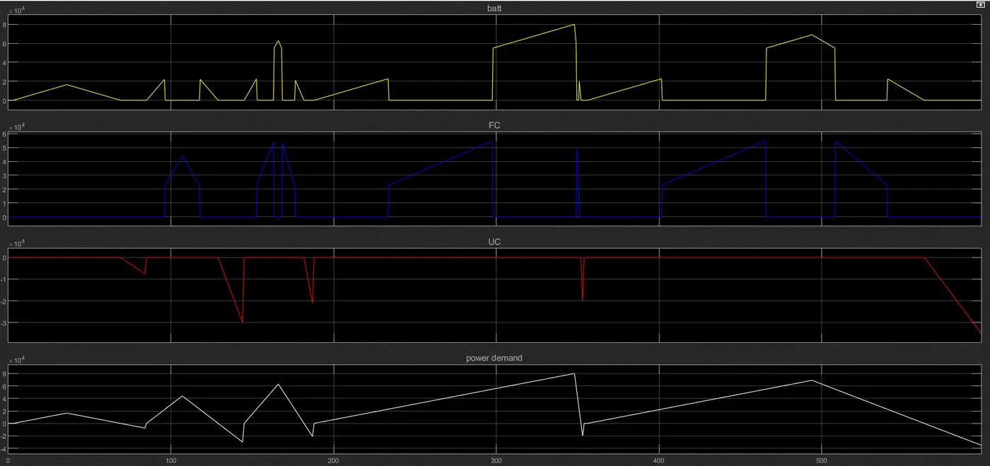
- Since the UC doesn't meet the nominal SOC criteria but the battery does, UC will not provide any propulsion and power demand beyond 55kW will be provided by the battery. UC will absorb all the negative power until it can satisfy its conditions to be used as a propulsion source again.
Case 6: SOC_UC > SOC_batt AND SOC_UC > SOC_nominal BUT SOC_batt < SOC_nominal:
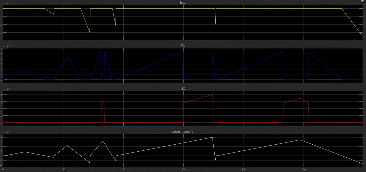
- Since the battery cannot provide propulsion power, any demand between 0 and 23kW will be provided by the FC instead. The battery will absorb all the negative power until it can satisfy its conditions to be used as a propulsion source again.