Drafting of various geometries using Chamfer, Fillet tool in AutoCad
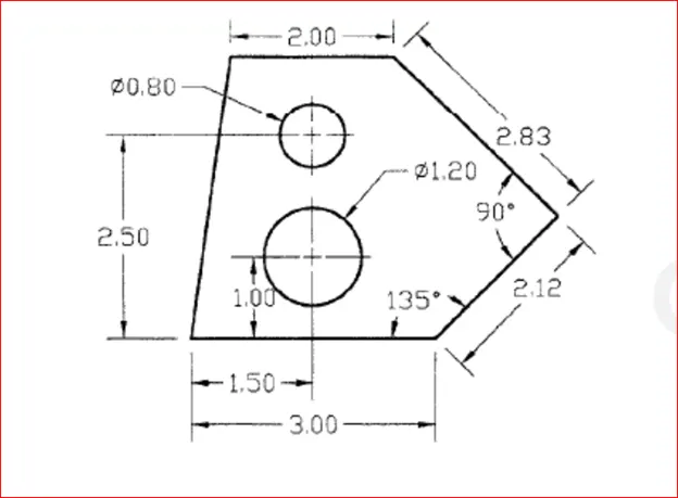
Q1) Aim: To draw the given Sketch in AutoCAD using Decimal
Introduction: Line, Circle, Dimension styles are used
Drawing1
Page Setup
Select New Page
Units – Decimal
Precision 0.00
Limits
Procedure
- Select line command
- Draw the line 3,0
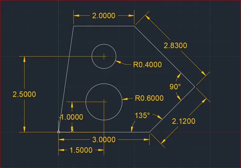
- Specify (@3,0), (@2.12 <45), (@2.83,135), (@2<180), close
- Select Circle with center (1.5,1) from origin with radius 0.60 and press enter
- Select circle with center (1.5,2.5) from the origin with radius 0.40 and press enter
- Type DIMESION STYLE in the command line
- Select modify and change Arrow size, Text size and Text height
- Type DIMENSION LINESR and select the starting and ending points to mark the dimensions
- Repeat this for all the dimensions and mark the measurements
Drawing 1 AutoCAD
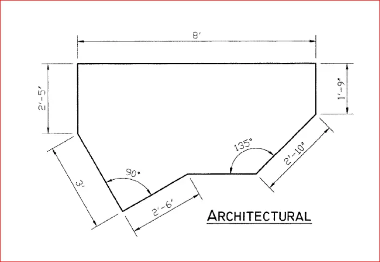
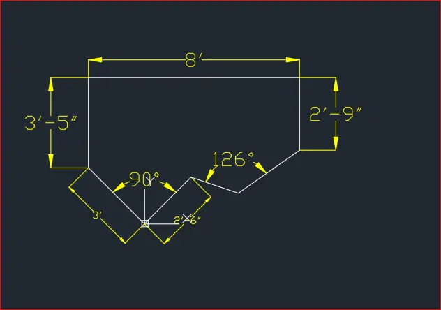
Q2 Aim: To draw the given Sketch in AutoCAD using Architectural
Introduction: Line, Circle, Mirror, Trim, Move, Mainly Rotate, Chamfer, Fillet, Move, offset etc. are used
Drawing 2
Page Setup
Select New Page
Units – Architectural
Precision 0’-0”
Limits
Procedure
- Select line command
- Specify 0,0 and (@ 2’6” <45) close command
- Select line command
- Specify 0,0 and (@3’<135)
- Specify (@3’5”<90)
- Specify (@8<0)
- Specify (@2’9”< 270)
- Specify (@2’10”< 225)
- Close the command
- Type DIMESION STYLE in the command line
- Select modify and change Arrow size, Text size and Text height
- Type DIMENSION LINESR and select the starting and ending points to mark the dimensions
- Repeat this for all the dimensions and mark the measurements
We are using the continuous method of drawing because few dimensions are not mentioned in the plan
Drawing2 AutoCAD
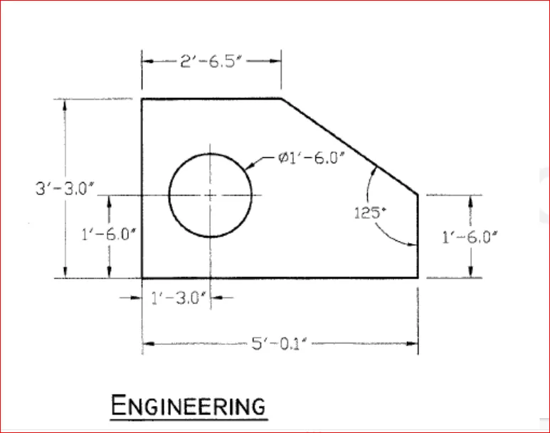
Q3 Aim: To draw the given Sketch in AutoCAD using Engineering
Introduction: Rectangle, Circle, Chamfer, All Dimension commands are used
Drawing 3
Page Setup
Select New Page
Units – Engineering
Precision 0’-0”
Limits
Procedure
- Select Rectangle command
- Specify first point 0,0
- Select dimension give length 5’0.1” and width 3.3”
- Select the chamfer
- Select the distance first chamfer length 2’6.51” and second chamfer length 1’9”
- Select first chamfer line
- Select second chamfer line
- Close the command
- Select radius and center command
- Specify center as 1’3”, 1’6”
- Give radius as 0.9”
- Type DIMESION STYLE in the command line
- Select modify and change Arrow size, Text size and Text height
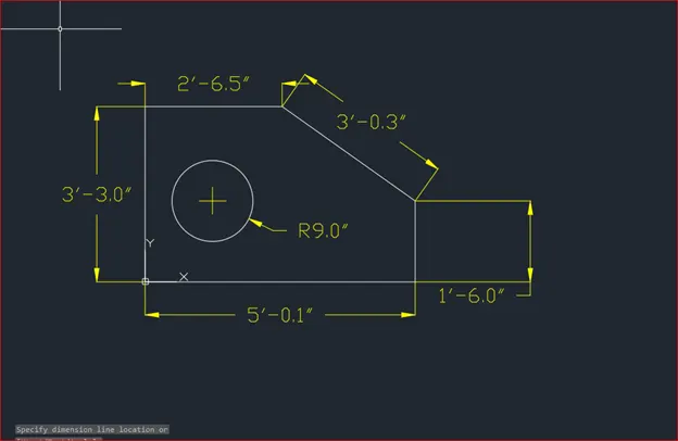
- Type DIMENSION LINESR and select the starting and ending points to mark the dimensions
- Repeat this for all the dimensions and mark the measurements
Drawing 3 AutoCAD
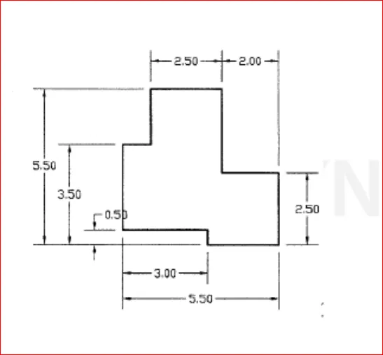
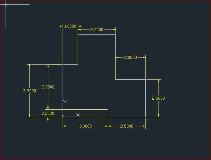
Q4 Aim: To draw the given Sketch in AutoCAD using Decimal
Introduction: Line and Dimension Linear commands are used
Drawing 4
Page Setup
Select New Page
Units – Decimal
Precision 0.00
Limits
Procedure
- Select line command
- Specify first point as 3,0
- Next point as 5.5,0
- Specify (@2.50<90), (@2<180), (@3<90), (@2.50< 180), (@2<270), (@1<180), (@3.00<270), (@3<0)
- Close the command
- Type DIMESION STYLE in the command line
- Select modify and change Arrow size, Text size and Text height
- Type DIMENSION LINESR and select the starting and ending points to mark the dimensions
- Repeat this for all the dimensions and mark the measurements
Drawing 4 Autocad
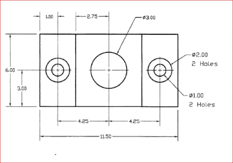
Q5 Aim: To draw the given Sketch in AutoCAD using Decimal
Introduction: Line, Circle and All Dimension commands are used
Drawing 5
Page Setup
Select New Page
Units – Decimal
Precision 0.00
Limits
Procedure
- Select Line Command
- Specify staring point as 0,0
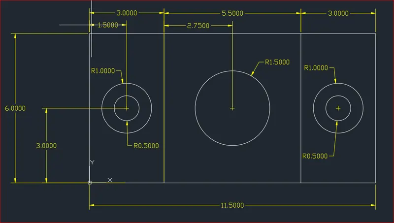
- Specify (@11.50<0), (@6<90), (@11.50<180), (@6<270)
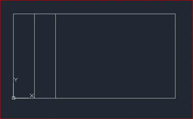
- Select Offset Command
- Select the line set offset distance as 1.50 and copy 2 lines
- Set ortho distance as 2.75 as copy 2 lines
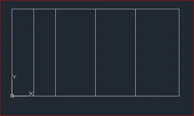
- Select the line set offset distance as 1.50 and copy 2 lines
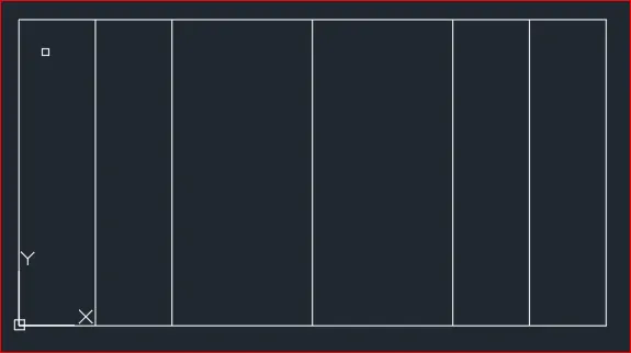
- Select the circle and radius command and draw 2 circles in rectangle 1, one of radius 0.50 and other as 1
- Repeat this for 3rd rectangle also
- For Rectangle 2 Draw circle as radius 1.5
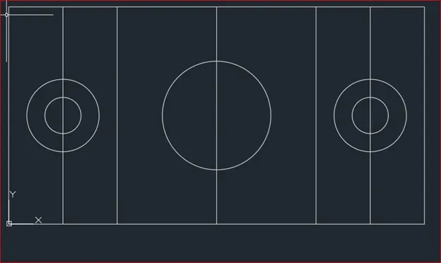
- Delete the unnecessary offset lines which are used as reference
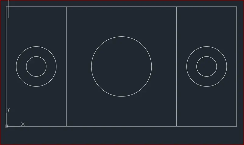
- Type DIMESION STYLE in the command line
- Select modify and change Arrow size, Text size and Text height
- Type DIMENSION LINESR and select the starting and ending points to mark the dimensions
- Repeat this for all the dimensions and mark the measurements
Drawing 5 AutoCAD
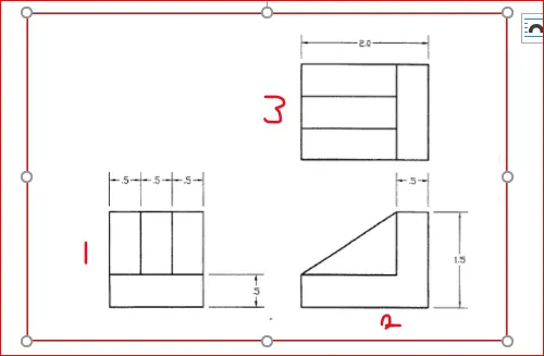
Q6 Aim: To draw the given figure in AutoCAD using Decimal
Introduction: Line, XLine, Offset, Trim and all Dimension commands are used
Drawing 6
Page Setup
Select New Page
Units – Decimal
Precision 0.00
Limits
Procedure
Procedure
- Select Line command
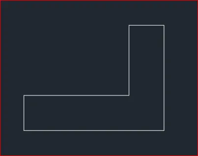
- For the Part 1
- Specify staring point as 0,0
- Specify (@1.5,0), (@2<180), (@1.50<90), (@2<0)
- Close the command
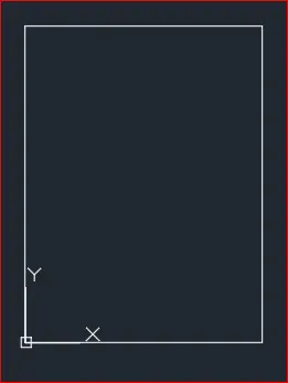
- Select Offset Command
- Select the bottom line and set offset distance as 0.50
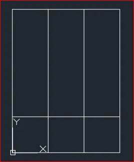
- Use the trim command and delete the middle lines
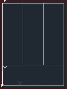
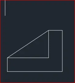
- For the Part 2
- Select the line command
- Specify any point
- Specify (@2,0), (@1.5<90), (@0.50<180),(@1<270) (1.5@180)(@0.50<270)
- Close the command
- Select the line command
- Join the line making the triangle
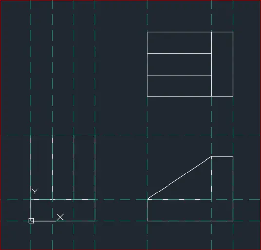
- For part 3
- Select line command
- Specify any point as starting point
- Draw line (@2<0), (@1.5<90), (@2<180), (@1.5< 270
- Select the bottom line and set offset distance as 0.50
- Draw two vertical lines
- And draw one horizontal line
- Use the trim command and delete the middle lines
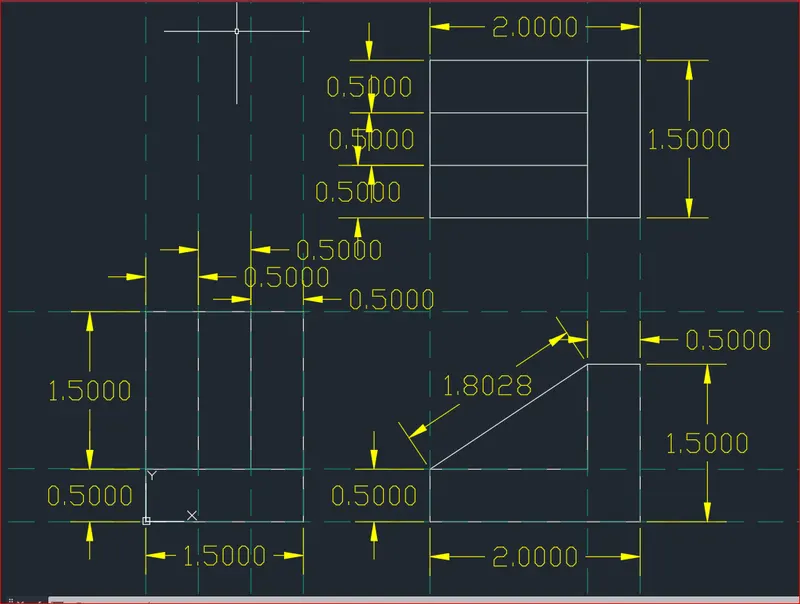
- Type DIMESION STYLE in the command line
- Select modify and change Arrow size, Text size and Text height
- Type DIMENSION LINESR and select the starting and ending points to mark the dimensions
- Repeat this for all the dimensions and mark the measurements
Drawing 6 AutoCAD
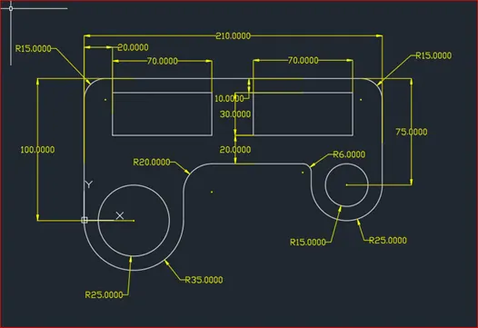
Q7 Aim: To draw the given Views in AutoCAD using Decimal
Introduction: Line, XLine, Offset, Trim and all Dimension commands are used
Drawing 7
Page Setup
Select New Page
Units – Decimal
Precision 0.00
Limits
Procedure
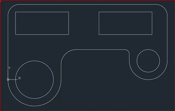
- Select line command
- Specify first point as 0,0
- Specify (@100<90), (@210<0), (@75<90)
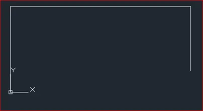
- Select the fillet command
- Select radius 15 and select the lines
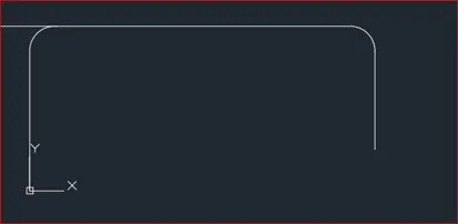
- Select the fillet command
- Select radius 15 and select the lines
- Select the top line and select ortho of 60
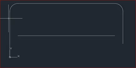
- Draw 2 reference lines at two ends one at 70 distance other at 50 distances
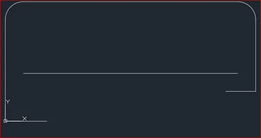
- At left line from center draw 2 circles one of 35 radius and other 25 radius
- At right from center draw 2 circles one of 25 radius and other 15 radius
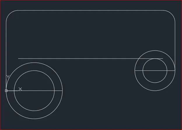
- Draw lines from circles ends to the above line for references
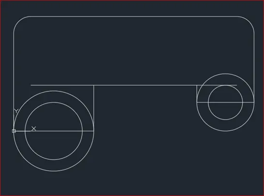
- Select the fillet command and give radius as 20
- Select the lines
- Select the fillet command again and give radius as 6
- Select the lines
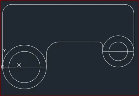
- Select the trim command and deleted the unwanted lines
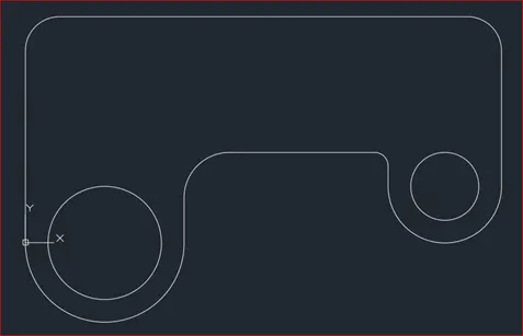
- Draw the reference lines using the ortho command
- Draw 2 rectangles
- Type DIMESION STYLE in the command line
- Select modify and change Arrow size, Text size and Text height
- Type DIMENSION LINESR and select the starting and ending points to mark the dimensions
- Repeat this for all the dimensions and mark the measurements
Drawing 7 AutoCAD
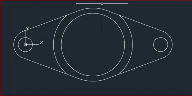
Q8 Aim: To draw the given Shape in AutoCAD using Decimal
Introduction: Line, Rectangle, Offset, Circle, Offset, Fillet, Trim and all Dimension commands are used
Page Setup
Select New Page
Units – Decimal
Precision 0.00
Limits
Procedure
- Select line command
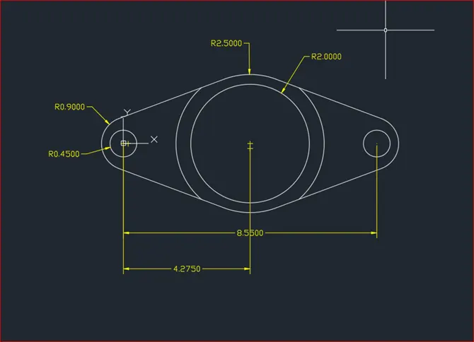
- Specify first point as 0,0 and draw 8.55,0
- Select the circle command and draw 2 circles and radius one as 0.90 and second as 0.45 with 2 line ends as center
- Using the center of line draw inner circle at as 2.0 and outer as 2.5 radius
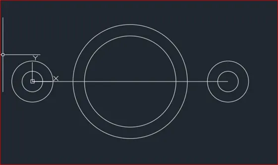
- Using line command draw tangents on to the circle
- Select trim and delete the unnecessary portions
- Select the fillet command and give radius as 0.9 and make fillet on the lines on to circle
- Delete the extra curves using trim command
- Type DIMESION STYLE in the command line
- Select modify and change Arrow size, Text size and Text height
- Type DIMENSION LINESR and select the starting and ending points to mark the dimensions
- Repeat this for all the dimensions and mark the measurements
Q9 Aim: To draw the given Shape in AutoCAD using engineering
Introduction: Circle, Arc, ALL dimension commands are used
Page Setup
Select New Page
Units – Engineering
Precision 0.00
Limits
Procedure
- Select line command
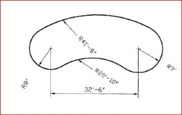
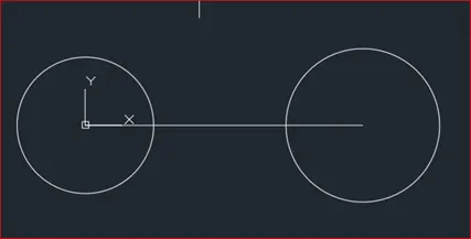
- Specify starting point as 0,0 and point 32’6”,0
- Using two-line ends draw 2 circles one on each side with radius 8’ and 9’
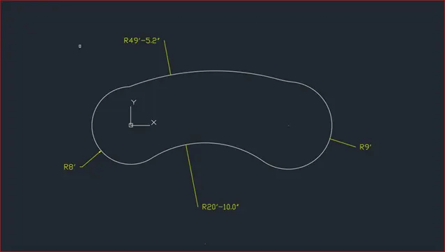
- Use the arc and radius option and select the 2 circles top points and give radius as 41’8” for above arc
- Use the arc and radius option and select the 2 circles below points and give radius as 20’ 10” for above arc
- Delete unnecessary lines using trim option
- Type DIMESION STYLE in the command line
- Select modify and change Arrow size, Text size and Text height
- Type DIMENSION LINESR and select the starting and ending points to mark the dimensions
- Repeat this for all the dimensions and mark the measurements
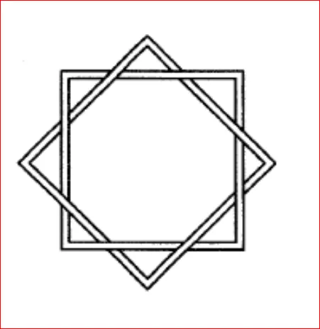
Q10 Aim: To draw the given Shape in AutoCAD using engineering
Introduction: Rectangle, rotate commands are used
Page Setup
Select New Page
Units – Engineering
Precision 0.00
Limits
Procedure
- Select Rectangle Command
- Specify staring point as 0,0
- Specify next point as (100,100)
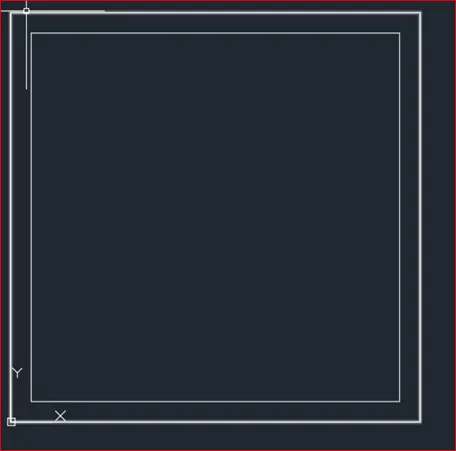
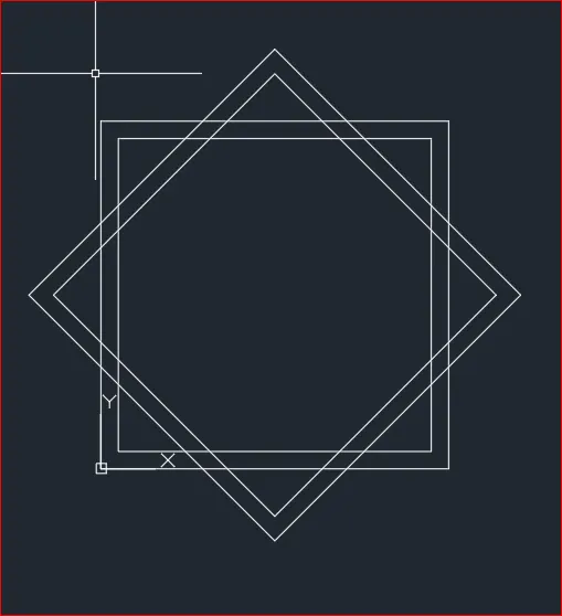
- Select ortho give a distance as 5
- Select rotate command and select copy and give angle 45
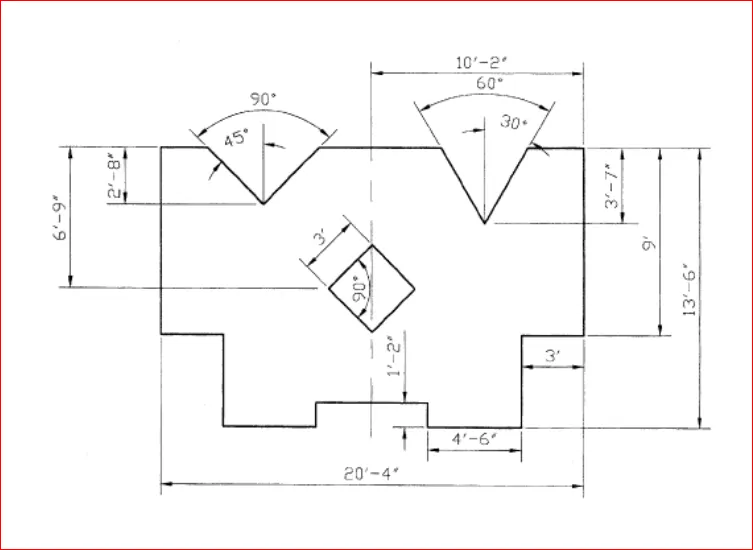
Q11 Aim: To draw the given Shape in AutoCAD using Architectural
Introduction: Line, Rectangle, Offset, Circle, Offset, Fillet, Trim and all Dimension commands are used
Page Setup
Select New Page
Units – Architectural
Precision 0.00
Limits
Procedure
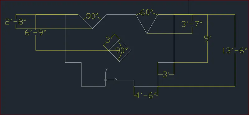
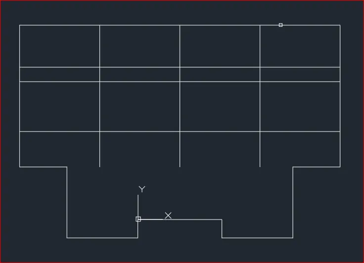
- Select Line command
- Turn on the orthomode
- Specify staring point as 0,0
- Specify 1’2” @- ve y axis
- Specify 4’6” @- ve x axis
- Specify 4’6” @+ ve y axis
- Specify 3’ @- ve x axis
- Specify 9’ @+ ve y axis
- Specify 20’4” as +x axis
- Specify 9’ @-ve y axis
- Specify 3’ @-ve x axis
- Specify 4’6” @-ve x axis
- Specify 1’2” @+ve y axis
- Close the command
- Select offset command distance as 3’7” and 2’8” from top
- Divide the top line into 4 equal parts 5’1” each
- Draw 2 lines at 5’1” and 15’3” using ortho
- Rotate Copy the line using the angle 30 on left line
- Rotate Copy the line using the angle 45 on left line
- for inner triangle length of 3’ and angle of 45
- move the square to the 6’9” using the ortho
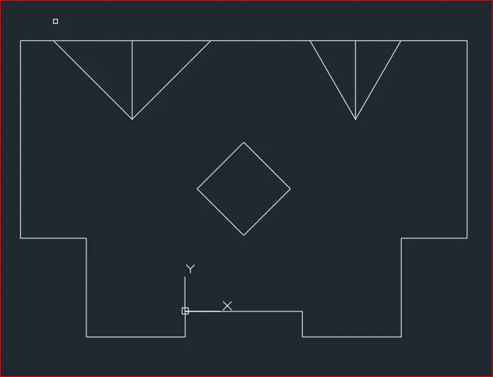
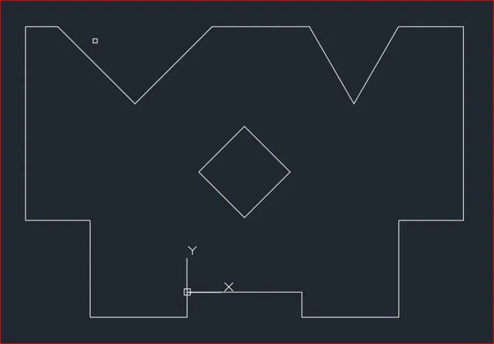
- using trim delete the unnecessary lines
- using fillet join the lines
- Type DIMESION STYLE in the command line
- Select modify and change Arrow size, Text size and Text height
- Type DIMENSION LINESR and select the starting and ending points to mark the dimensions
- Repeat this for all the dimensions and mark the measurements