Creating a Floor plan, Footing detail and Isometric view using AutoCad
Master’s Certification Program in
High Rise Building Design & Analysis
Creating a Floor Plan, footing detail and Isometric view Using AutoCAD
Challenge 2
Submitted
By
Naray Kiran Bhargav
Q1) Creating the following in the AutoCAD
Ans: The following are the commands used in this challenge
- Line
- Rectangle
- Trim
- Mirror
- Copy
- Move
- Dimension Style
- Dimension Linear
- Dimension Aligned
- Text
- Text Edit
- Escape
- Ortho
- Isometric
Before starting the drafting page setup plays a key role
Page Set up
- Open AutoCAD
- In command line type STARTUP
- Give input as 1
- Then go to ribbon main bar and select New
- In the Create New drawing dialog bx
- Set the units
- Set the precession
- Then click okay
- Create the section of load bearing wall over spread footing
Introduction: The required cross section is created primarily by using the Line and Rectangle tools
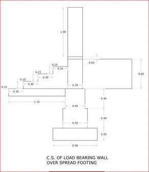
Procedure:
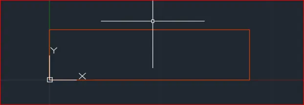
Step 1:
- Type RECTANG in the command box
- Specify the first point as 0,0
- Then select dimensions in the command line or type d and press enter
- Specify the length 0.90
- Specify the breadth 0.25
- Head the cursor towards +ve x,y quadrant and click enter
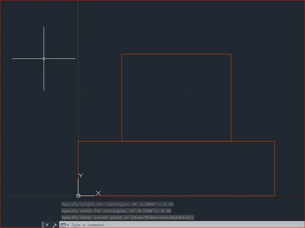
Step 2:
- Type RECTANG in the command box
- Specify the first point as 0.20, 0.25 in command line
- Then select dimensions in the command line or type d and press enter
- Specify the length 0.50
- Specify the breadth 0.40
- Head the cursor towards +ve x,y quadrant and click enter
Step 3:
- Type RECTANG in the command box
- Specify the first point as 0.25, 0.65 in command line
- Then select dimensions in the command line or type d and press enter
- Specify the length 0.40
- Specify the breadth 0.40
- Head the cursor towards +ve x,y quadrant and click enter
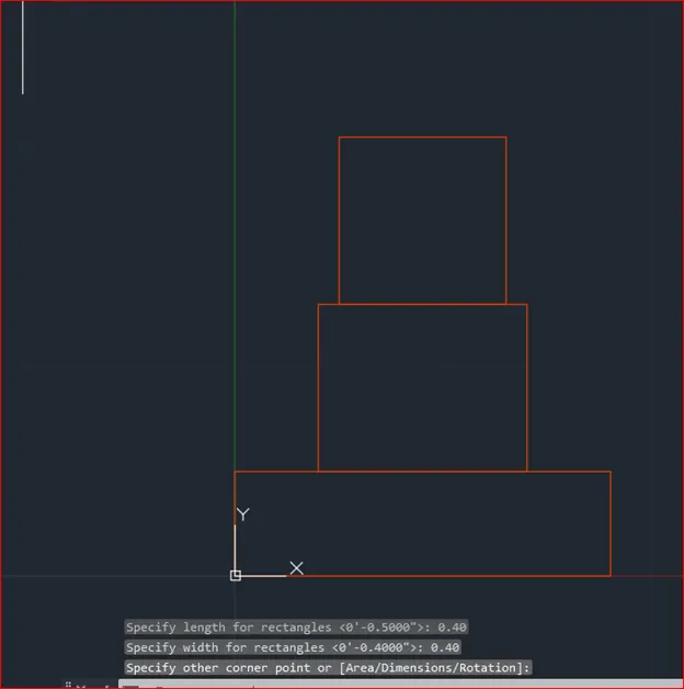
Step 4:
- Type RECTANG in the command box
- Specify the first point as 0.30, 1.05 in command line
- Then select dimensions in the command line or type d and press enter
- Specify the length 0.30
- Specify the breadth 0.60
- Head the cursor towards +ve x,y quadrant and click enter
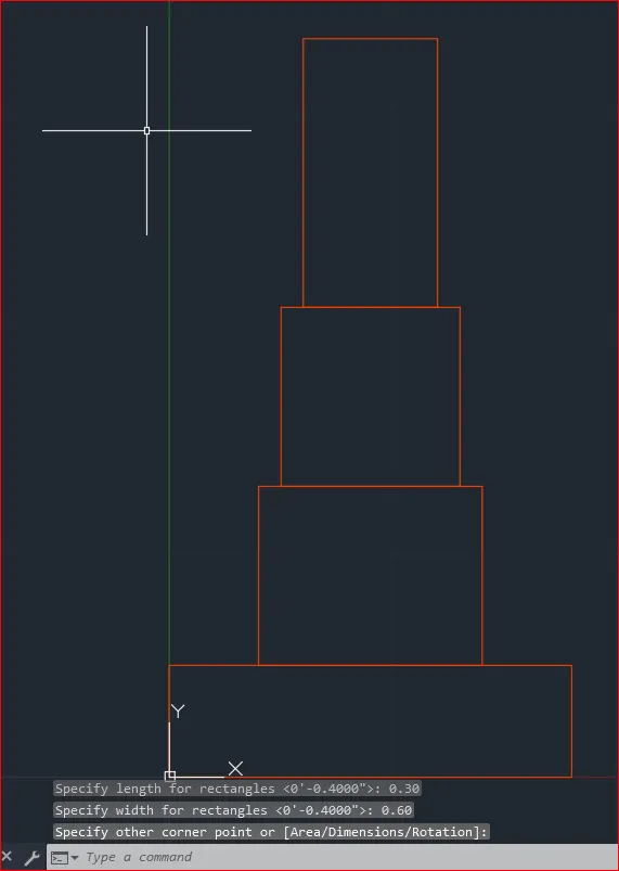
Step 5:
- Type RECTANG in the command box
- Specify the first point as 0.30, 1.65 in command line
- Then select dimensions in the command line or type d and press enter
- Specify the length 0.30
- Specify the breadth 0.05
- Head the cursor towards +ve x,y quadrant and click enter
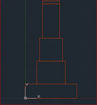
Step 6:
- Type RECTANG in the command box
- Specify the first point as 0.30, 1.70 in command line
- Then select dimensions in the command line or type d and press enter
- Specify the length 0.30
- Specify the breadth 1.0
- Head the cursor towards +ve x,y quadrant and click enter
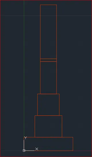
Step 7:
- Type RECTANG in the command box
- Specify the first point as 0.25, 1.05 in command line
- Then select dimensions in the command line or type d and press enter
- Specify the length 1.15
- Specify the breadth 0.15
- Head the cursor towards left and click enter
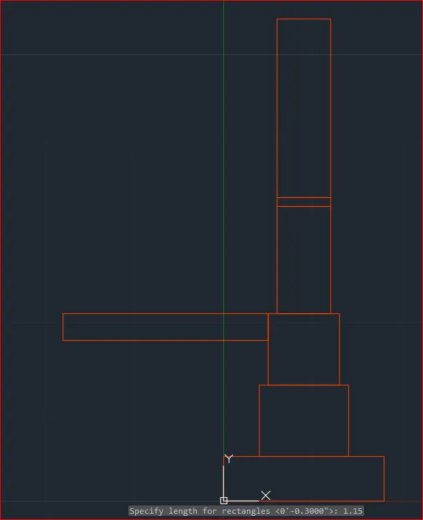
Step 8:
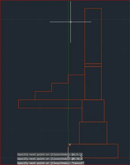
- select the line tool by typing LINE in command line
- Specify the first point as -0.60, -1.05 in the command line
- type next Coordinate as @0,0.15 press enter
- type next Coordinate as @0.30,0 press enter
- type next Coordinate as @0,0.15 press enter
- type next Coordinate as @0.30,0 press enter
- type next Coordinate as @0,0.15 press enter
- type next Coordinate as @0.30,0 press enter
- Press escape ESC to close the command
Step 9:
- Select the trim tool by Entering TR in command line
- Select Edge and click on No extend
- Select the lines need to be deleted
- Close the command
Step 10:
- Type DIMESION STYLE in the command line
- Select modify and change Arrow size, Text size and Text height
- Type DIMENSION LINESR and select the starting and ending points to mark the dimensions
- Repeat this for all the dimensions and mark the measurement
Result
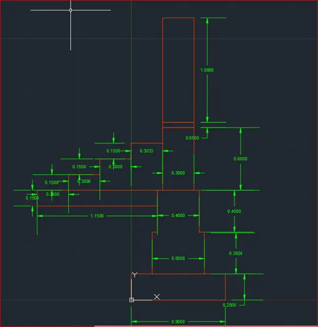
2. Create the section of ISOLATED FOOTING
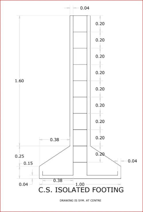
Step 1:
- select the line tool by typing LINE in command line
- Specify the first point as 0,0 in the command line
- type next Coordinate as @1.00,0 press enter
- type next Coordinate as @0,0.15 press enter
- type next Coordinate as @-0.38,0.25 press enter
- type next Coordinate as @0,1.60 press enter
- type next Coordinate as @-0.24,0 press enter
- type next Coordinate as @0, -1.60 press enter
- type next Coordinate as @-0.38, -0.25press enter
- Close the Command
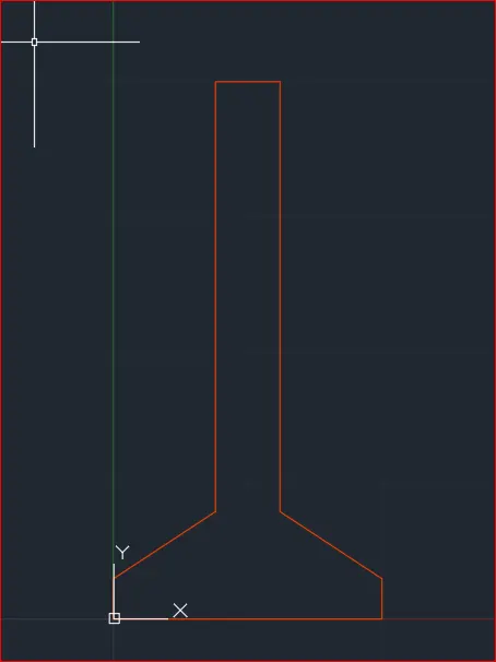
Step 2:
- select the line tool by typing LINE in command line
- Specify the first point as 0.42,2.0 in the command line
- type next Coordinate as @0, -1.96 press enter
- type next Coordinate as @-0.38,0 press enter
- type next Coordinate as @0,0.04 press enter
- Press ESC to Close the Command
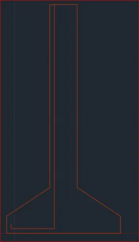
Step 3:
- select the Mirror tool by typing MIRROR in command line
- Select the object in step 2
- Specify the points and make the mirror
- Don’t delete the source object
Mirror makes the work easy
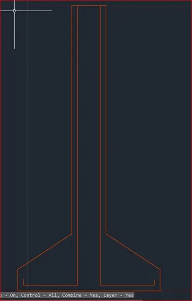
Step 4:
- select the OFFSET tool by typing MIRROR in command line
- Enter 0.20 as offset distance in the command line.
- Select the topmost line of the footing drawing
- Don’t delete the source object
- Repeat the process 8 times same process
- Press ESC to close the OFFSET command.
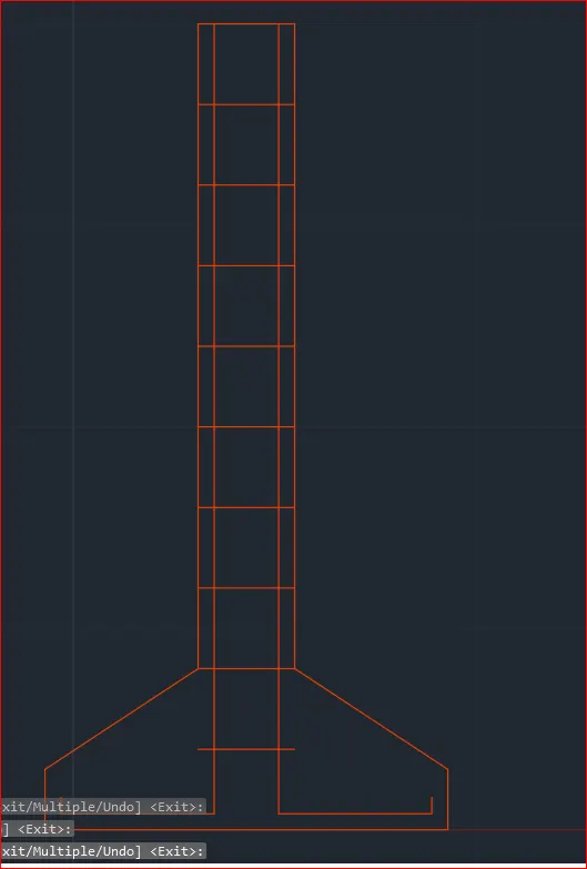
Step 5:
- Select the trim tool by Entering TR in command line
- Select Edge and click on No extend
- Select the lines need to be deleted
- Close the command
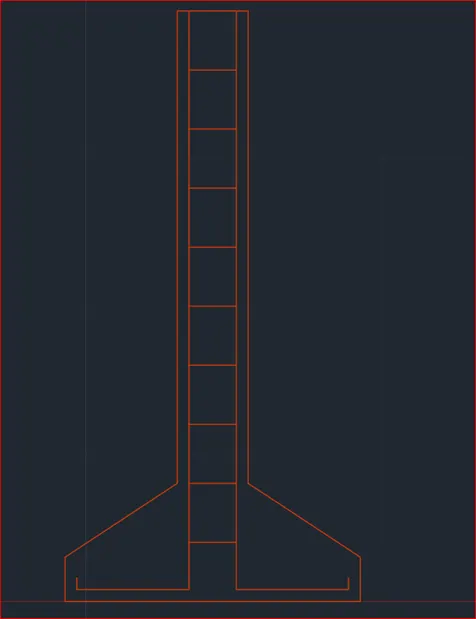
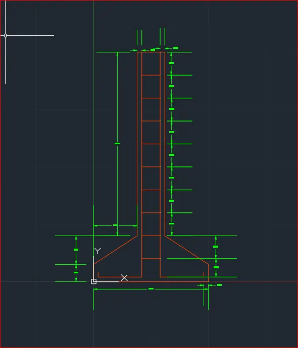
Step 6:
- Type DIMESION STYLE in the command line
- Select modify and change Arrow size, Text size and Text height
- Type DIMENSION LINESR and select the starting and ending points to mark the dimensions
- Repeat this for all the dimensions and mark the measurements
Result
3. Line Diagram of a Two Room Building
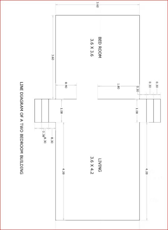
Step 1:
- Select the line tool by entering Line Command
- As it is a Regular shape make the Ortho mode on
- Specify the first point as 0,0 in the command line
- type next Coordinate as 3.60 in + ve x direction
- type next Coordinate as 3.60 in - ve y direction
- type next Coordinate as 0.90 in + ve x direction
- type next Coordinate as 1.0 in - ve y direction
- type next Coordinate as 0.90 in - ve x direction
- type next Coordinate as 4.20 in - ve y direction
- type next Coordinate as 3.60 in - ve x direction
- type next Coordinate as 4.20 in + ve y direction
- type next Coordinate as 0.90 in - ve x direction
- type next Coordinate as 1.0 in + ve y direction
- type next Coordinate as 0.90 in + ve x direction
- type next Coordinate as 3.60 in + ve y direction
- click close in the command
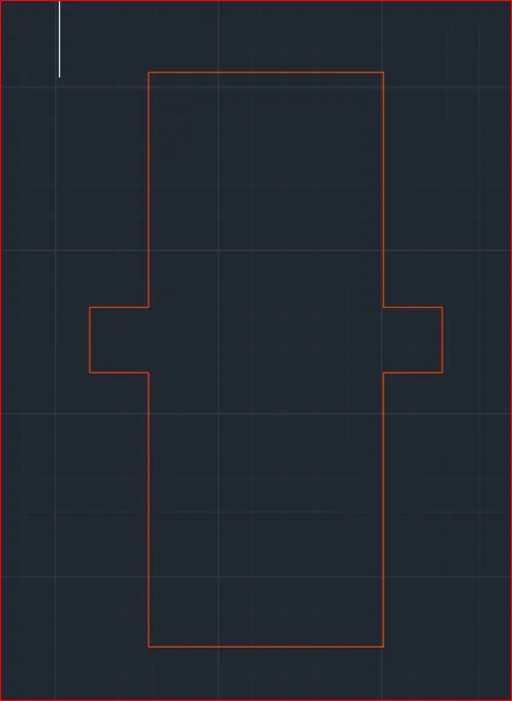
Step 2:
- Select the OFFFSET tool by entering OFFSET in command line
- Enter 0.30 as offset distance in the Command line
- Specify the stairs at equal distance
- Press Esc to Cancel the Command
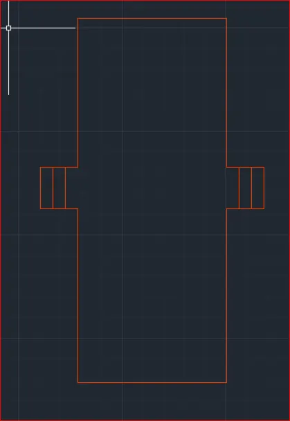
Step 3:
- To draw the partition walls
- Select the line tool
- Ttype 1.80 in -ve x direction
- Type 0.90in +ve x direction
- Type ESC and close the Command
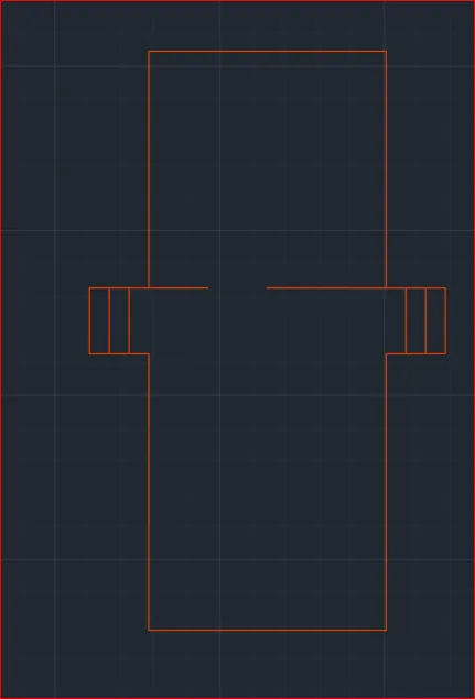
Step 4:
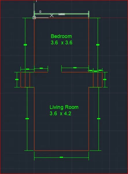
- Type DIMESION STYLE in the command line
- Select modify and change Arrow size, Text size and Text height
- Type DIMENSION LINESR and select the starting and ending points to mark the dimensions
- Repeat this for all the dimensions and mark the measurements
Result
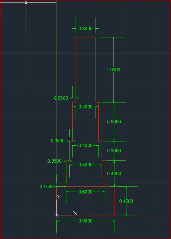
4) C.S. OF LOAD BEARING WAL SHOWING FOUNDAION DETAILS
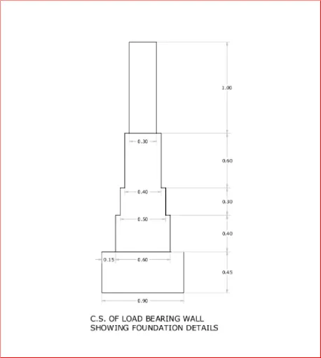
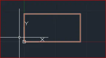
Step 1:
- Type RECTANG in the command box
- Specify the first point as 0,0
- Then select dimensions in the command line or type d and press enter
- Specify the length 0.90
- Specify the breadth 0.45
- Head the cursor towards +ve x,y quadrant and click enter
Step 2:
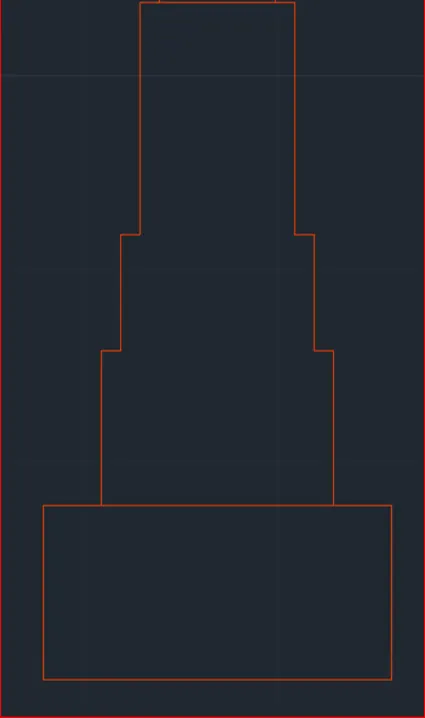
- select the line tool by typing LINE in command line
- As it is a linear shape use the Ortho Mode on
- Specify the first point as 0.15,0.45 in the command line
- type next Coordinate as 0.40 in the +ve y direction
- type next Coordinate as 0.05 in the +ve x direction
- type next Coordinate as 0.30 in the +ve y direction
- type next Coordinate as 0.05 in the +ve x direction
- type next Coordinate as 0.40 in the +ve x direction
- type next Coordinate as 0.60 in the -ve y direction
- type next Coordinate as 0.05 in the +ve x direction
- type next Coordinate as 0.30 in the -ve y direction
- type next Coordinate as 0.05 in the +ve x direction
- type next Coordinate as 0.40 in the -ve y direction
- Press ESC to cancel the command
Step 3 :
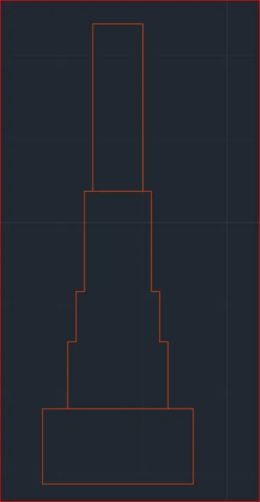
- select the line tool by typing LINE in command line
- Specify the first point as 0.30,1.75 in the command line
- type next Coordinate as @0,1.0
- type next Coordinate as @0.30 ,0
- type next Coordinate as @0 ,-1.0
- Press Esc to cancel the LINE command
Step 4:
- Type DIMESION STYLE in the command line
- Select modify and change Arrow size, Text size and Text height
- Type DIMENSION LINESR and select the starting and ending points to mark the dimensions
- Repeat this for all the dimensions and mark the measurements
Result
5. Isometric View
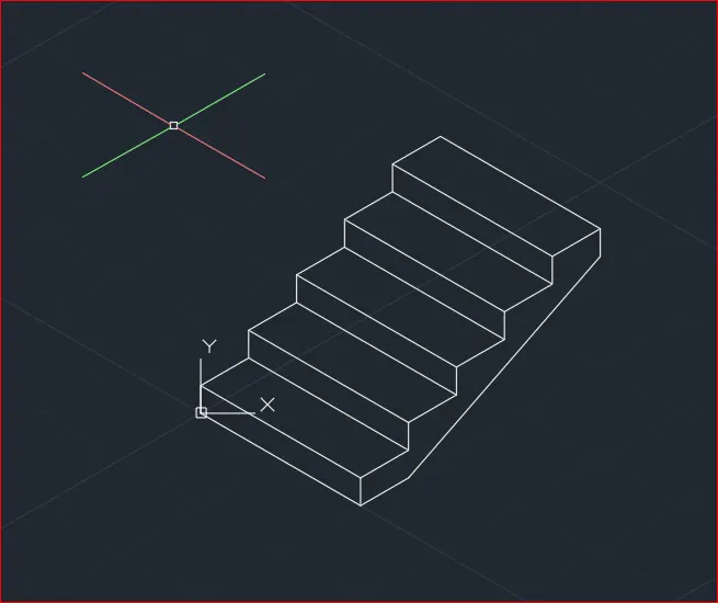
- View of Steps
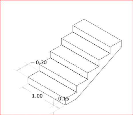
Step 1:
- Turn on isometric Drafting
- Select isoplane Left
- Turn on the ortho
- Select the line Command
- Specify the First point as 0,0
- type next Coordinate as 1 in the right direction
- type next Coordinate as 0.15 on the top direction
- type next Coordinate as 1 in the left direction
- type next Coordinate as 0.15 on the Downward direction
- Click close the command line
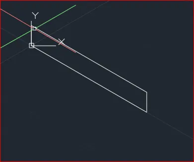
Step 2:
- Select the isoplane right
- Select line tool by entering LINE command
- Keep the ortho mode ON
- Specify first point as top corner of the rectangle drawn in step1
- Type next coordinate as 0.30 in the right direction
- Press Esc to cancel the command
- Repeat the same process for all the 3 corners except origin
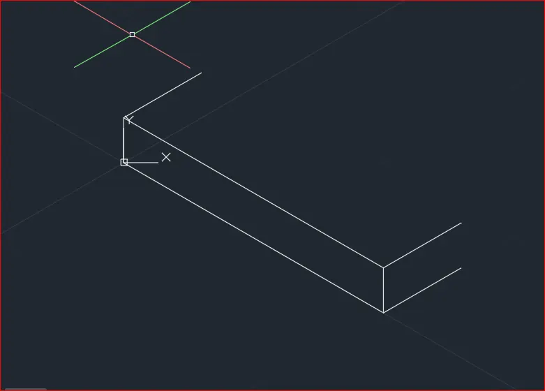
Step 3:
- Select the copy tool
- Select line entire figure except the length 030 at bottom of the stari case
- Specify the base point and copy it 3 times
- Press ESC ro cancel the command
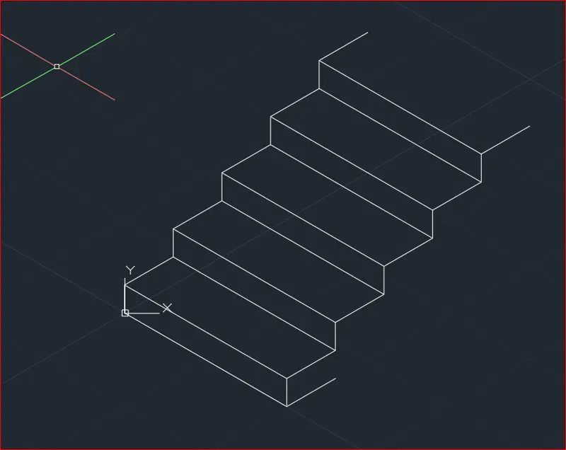
Step 4:
- Select the line tool
- Join the top two lines
- From right corner draw 0.15 downwards
- Then join the first step line to the top line
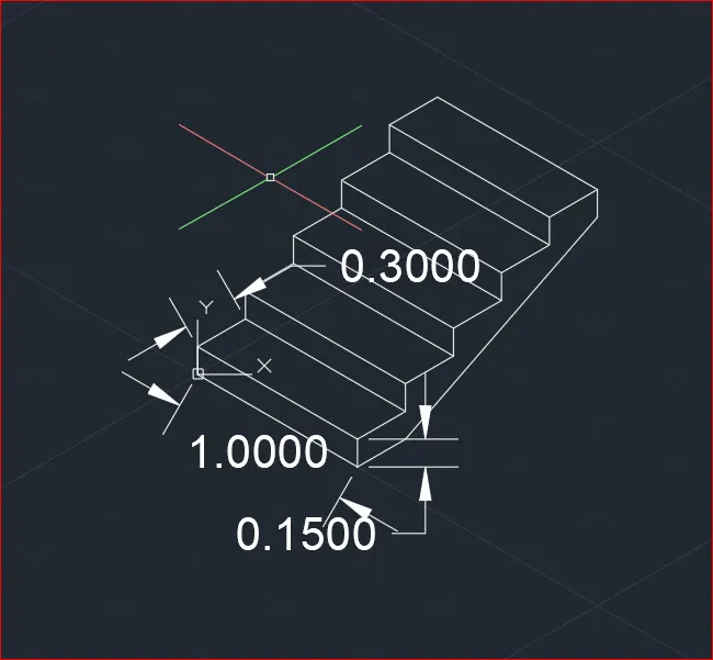
Step 5 :
- Type DIMESION STYLE in the command line
- Select modify and change Arrow size, Text size and Text height
- Type DIMENSION LINESR and select the starting and ending points to mark the dimensions
- Repeat this for all the dimensions and mark the measurements
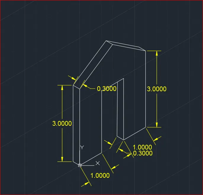
2. GABBLE WALL
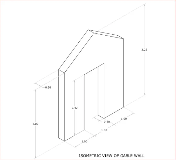
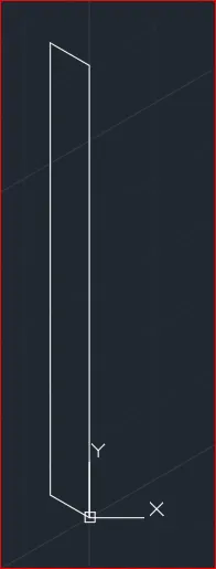
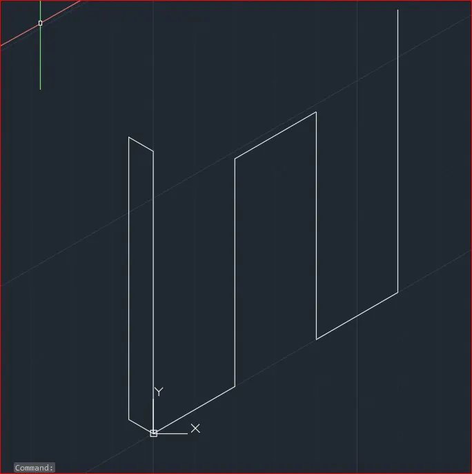
Step 1:
- Turn on Isometric Drawing
- Select isometric left
- Turn on the ortho and Select line command
- Specify the starting point as 0,0
- Then next point as 3 in the upward direction
- Then 0.30 in left direction
- Then 3 in the downward direction
- Esc to close the command
Step 2:
- Select isometric Right
- Turn on the ortho and Select line command
- Specify the starting point as top right corner of the above drawn rectangle
- Then next point as 3 in the right direction
- Then next point as 3 in the downward direction
- Then next point as 1 in the left direction
- Then next point as 2.42 in the upward direction
- Then next point as 1 in the Left direction
- Then next point as 2.42 in the downward direction
- Then next point as 1 in the left direction
- Esc to close the command
Step 3:
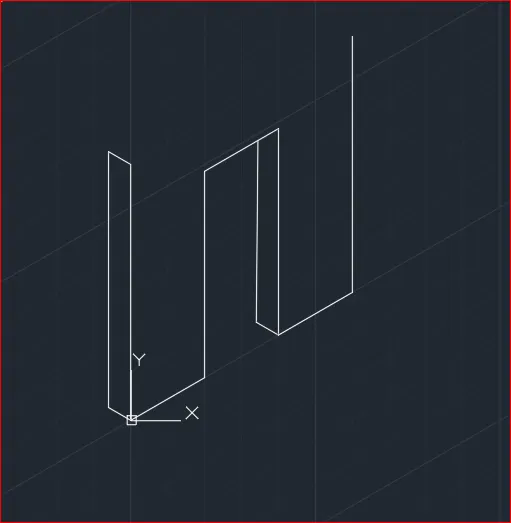
- Select the isophane left
- Turn on the ortho and Select line command
- Specific the first corner of the door opening
- Then next point as 0.30 in the left direction
- Then next point as 2.12 in the upward direction
- Esc to close the command
Step 4:
- Select the isoplane right
- Turn on the ortho and Select line command
- Specify the first point at midpoint 0f the top line
- Specify next point as 1 in the upward direction
- Esc to close the command
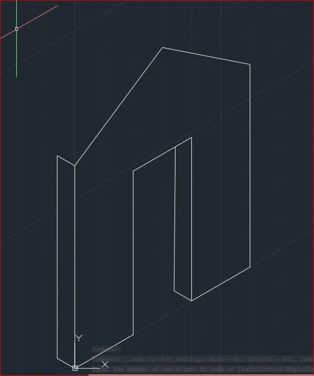
Delete the extra lines
Step 5 :
- Copy the upper paart to 0.30 distance
- Using the line tool join the necessary vertices
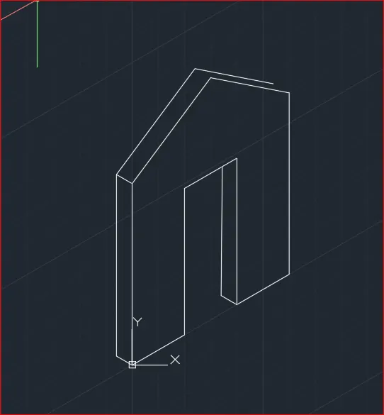
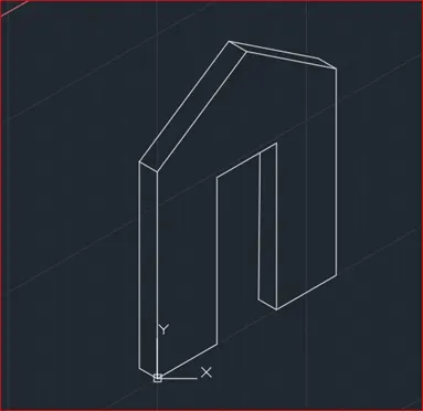
Result