Creating a Residence Layout, Seating plan, Toilet and Utility room plan using AutoCad
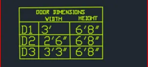
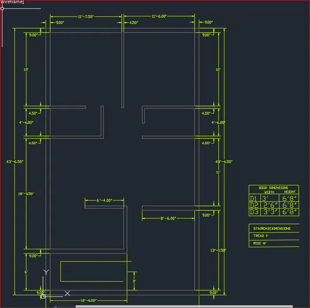
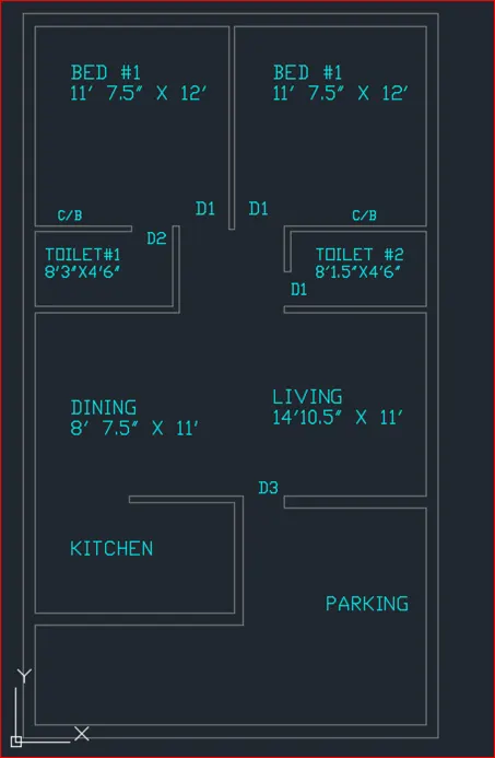
Q1) Residence Plan: Sketch the layout of a residence as shown in the Figure 1. Consider all dimensions as reference to sketch the unit plan. Also, the text in the layout are only for reference. Assume the missing dimensions. Also, refer the schedule for size of the doors
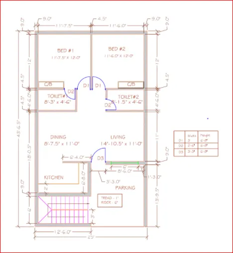
Aim: Sketch the layout of a residence as shown below. Consider all dimensions as reference to sketch the unit plan
Introduction: Drawing the necessary residence layout plan using AutoCAD and necessary commands and some necessary series and procedures has to be followed.
Page Setup
Create a new page
Choose Advanced settings
Specify the limits
Set engineering
Precision 0’0”
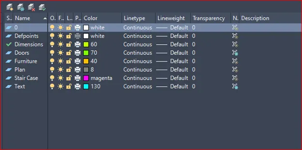
Layers Setup
Make the necessary layer arrangements
Procedure:
Step 1:
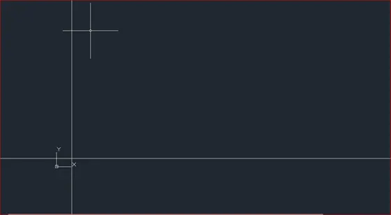
Draw the reference lines using the
XLine command
H for horizontal and V for vertical
Step 2:
Using the
Line, Offset, Fillet, Commands Draw the necessary plan
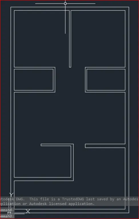
Step 3:
Using Offset, Trim and Erase commands make the necessary portions for Doors in the walls
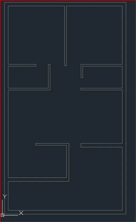
Step 4:
Using the Line, Circle, and trim commands draw the necessary Doors
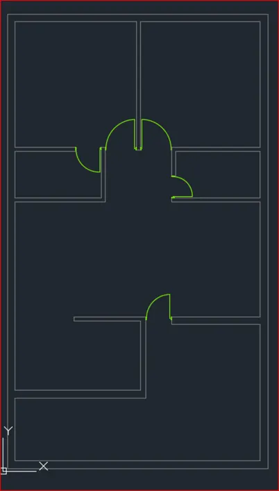
Step 5:
With the help of the Rectangle and Line Tool draw the cupboards and Kitchen furniture
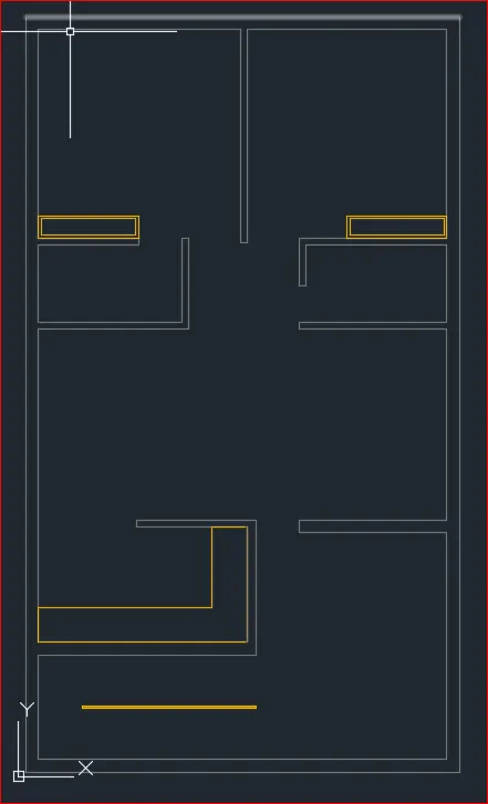
Step 6:
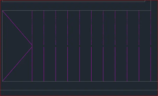
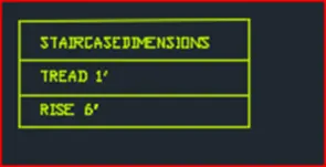
Using the Line, offset and Trim Tools draw the necessary staircase and make necessary corrections.
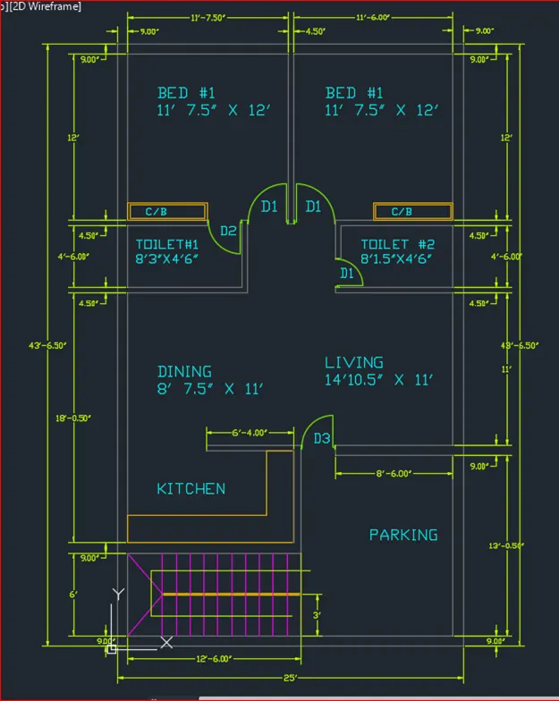
DOOR AND STAIR CASE DIMENSIONS
Step 7
Using the DIMESION STYLE in the command line
Select modify and change Arrow size and text size
Type DIMENSION LINEAR and select the starting and ending points to mark the dimensions Repeat this for all the dimensions and mark the measurements
Step 8:
Using the TEXT STYLE in the command line
Select modify and change Arrow size and text size
Type DIMENSION LINEAR and select the starting and ending points to mark the dimensions Repeat this for all the dimensions and mark the measurements
AutoCAD Final Plan
Q 2 ) Sketch the seating plan for an outdoor canopy. Assume the dimensions for the seating. Also, consider the dimensions in mm
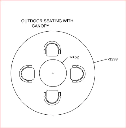
Aim: To Draw the required furniture i.e., Outdoor canopy assuming the necessary dimensions in mm
Introduction: Drawing the necessary residence layout plan using AutoCAD and necessary commands and some necessary series and procedures has to be followed.
Page setup
Create a new page
Choose Advanced settings
Specify the limits
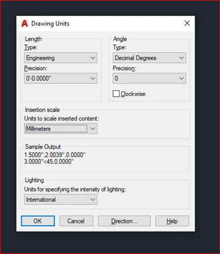
Set engineering
Select units to millimeters
Precision 0’-0.000”
Apply
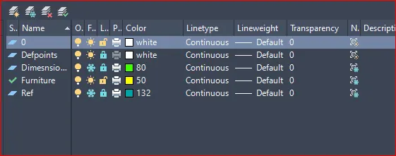
Layers Setup
Make the necessary layer arrangements
Step 1:
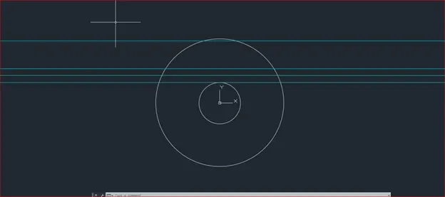
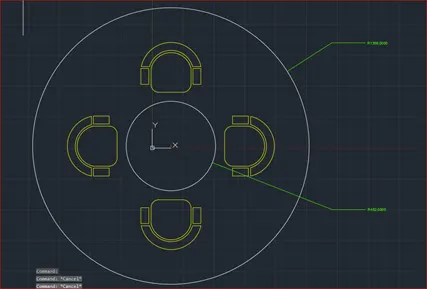
Using the circle radius command draw 2 circles inner circle of radius 452 mm and outer circle radius as 1398 mm

Step 2:
Using the XLine command draw the reference lines horizontally using offset make some reference lines
Step 3 To Draw Sofa
Step 3a:
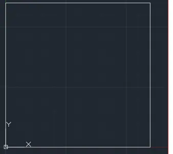
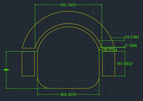
Using the Line command with length 404.2 mm and breadth 404.2mm draw a rectangle
Step 3b:
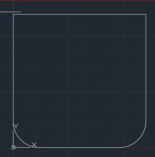
Using the fillet command and radius 6” make the filled for the bottom section of the rectangle
Step 3c:
Using the 3-point Arc Command Draw the arc
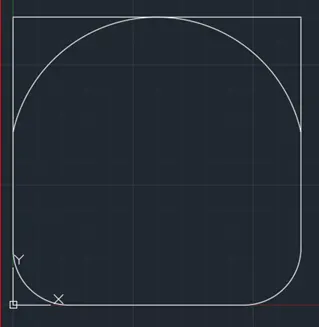
Step 3d:
Using the trim command delete the unwanted things
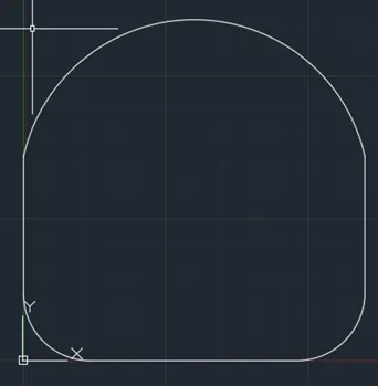
Step 3e:
Using the offset command with distance 20 mm make the necessary offsets
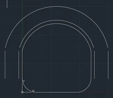
Step 3f:
Using the line and offset commands draw the lines joining the open ends
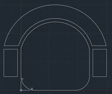
Step 3g:
Mark the dimensions using the dim linear command
Step 4:
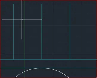
Using the drawn reference lines draw lines as shown in the figure
Step 5:
Using the drawn reference lines draw lines as shown in the figure
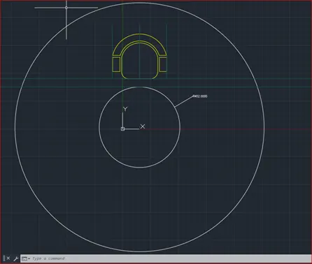
Copy the sofa to the Centre of the dimension
And scale it is using the scale command as shown in the figure
Step 6:
Using the Mirror command copy the sofa as required
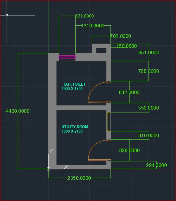
Q3) Sketch the part plan for the toilers and utilities room. Consider the outer wall thickness as 300mm and binner wall thickness as 150mm. Also, assume the missing dimension, Texts, dimensions, and hatches are
only for references. Also, symbols for toilets and w/c are also for references.
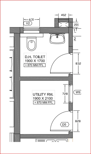
Aim: Sketch the part plan for the toilers and utilities room. Consider the outer wall thickness as 300mm and inner wall thickness as 150mm.
Introduction: Drawing the necessary residence layout plan using AutoCAD and necessary commands and some necessary series and procedures must be followed.
Page Setup
Create a new page
Choose Advanced settings
Specify the limits
Set engineering
Select units to millimeters
Precision 0’0”
Apply
Layers Setup
Make the necessary layer arrangements
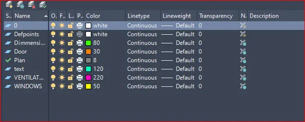
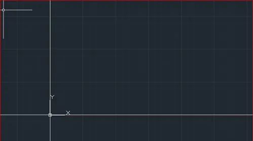
Step 1:
Using the XLine command draw horizontal and vertical lines
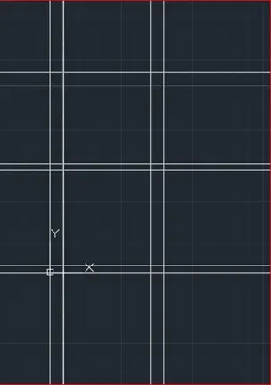
Step 2:
Using the offset command draw horizontal and vertical lines as per the plan given
Step 3:
Using the line offset command draw the lift portion
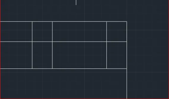
Step 4:
Using the trim command make the necessary actions and trim the unnecessary portions.
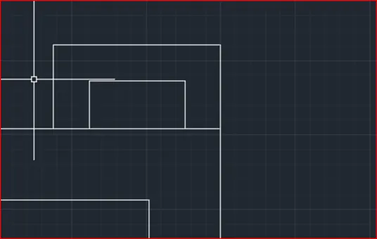
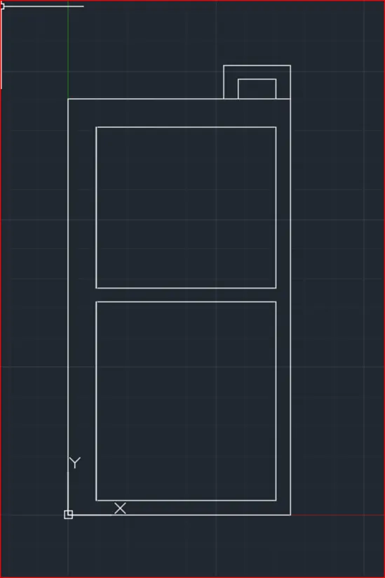
Step 5:
Using the trim command make the necessary spaces for the door, windows, and ventilators.
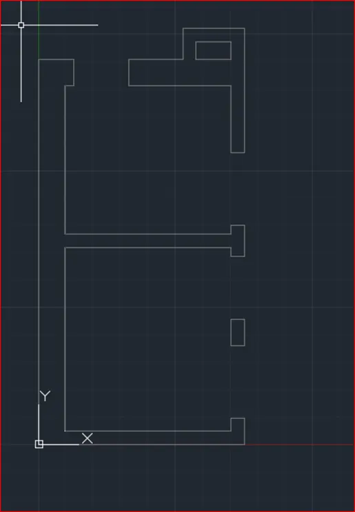
Step 6:
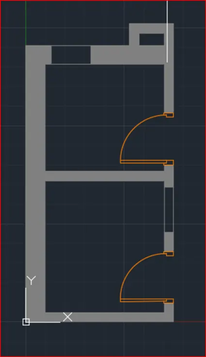
Using the Line, Circle, and trim commands draw the necessary Doors
Step 7:
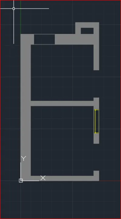
Using the Line and trim commands draw the necessary Window
Step8:
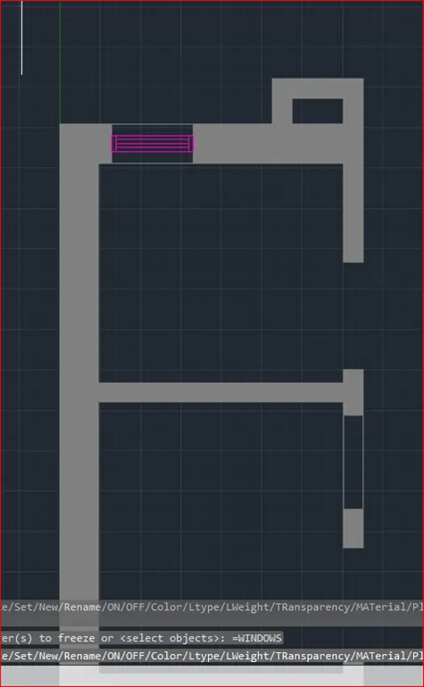
Using the Line and trim commands draw the necessary Ventilator
Step 9:
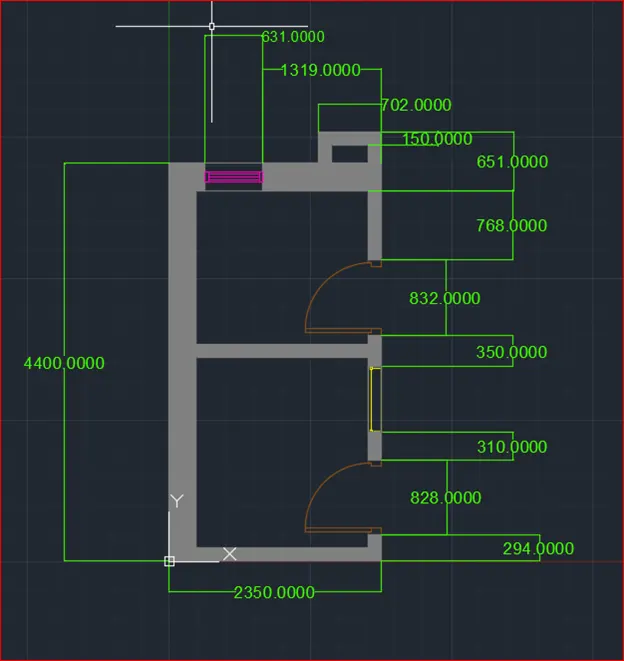
Using the DIMESION STYLE in the command line
Select modify and change Arrow size and text size
Type DIMENSION LINEAR and select the starting and ending points to mark the dimensions Repeat this for all the dimensions and mark the measurements
Step 10:
Using the TEXT STYLE in the command line
Select modify and change Arrow size and text size
Type DIMENSION LINEAR and select the starting and ending points to mark the dimensions Repeat this for all the dimensions and mark the measurements
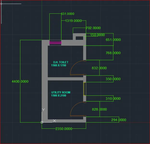
Final AutoCAD Drawing