Drafting of various geometries using Chamfer, Fillet tool in AutoCad
AIM:
DRAFTING IN VARIOUS GEOMETRIES USING CHAMPER ,FILLET TOOLS AUTOCAD:
INTRODUCTION:
autoCAD offers various tools to platform different tasks. the various tools which are used for drafting in this project are breifly discribed here. these tools include- modification tools:champer tool,fillet ,ofset ,rotate object sanping,trim and extend, lengthen,mirror,and join
CHAMPER:
Abevel or chamfer is:
*An angled line that means the endpoints of two straight 2D objects.
*A sloped transition between two surface or adjacent faces on a 3Dsolid.
the distance and angle that you specify are applied in the order that you select the objects.
command use champer.
FILLET
The fillet tool helps form round corner between any two entoties that form a sharp vertex.
A fillet can be created between two objects of the same or different object types .2D polyline ,arcs ,circles,ellipses,elliptical arcs,line rays,splines,and xlines
command used :FILLET
OFFSET:
Creates concentric circles,parallel lines and paralell curves.
command use :OFFSET
ROTATE:
Used to rorate object in our drawing arround a specified base point to determine the angle of rotation we can enter an angle value,drag using cursor or specified a refernce angle to absolute angle
command used :ROTATE
OBJECT SNAP:
Object snap provide a way to specify precise locations on objects whenever you are prompted for a point within a command
command use :OS...... object snap :short key used F3
QNS1) To draft the following geometry using decimal system of units:
PROCEDURE :
Type UN and press enter
under drawing units, select the desired unit that is decimal
type L in the command line and press enter
specify first point :1,1
specify next point:@3,0
specify next point:@2.12<45
specify next point:@2.83<135
specify next point:@-2,0
specify next point:@0,-2.5
type L in the command line and press enter
specify first point :a
specify next point:@1.5,0
specify next point:@0,1
specify next point:@0,1.5
type c and press enter
specify center point of circle:c
specify radius of circle:.60
type c and press enter
specify center point of circle:d
specify radius of circle:.40
after drawing circle delete the lines ab,bc and cd
give the dimensions as per the drawing using dimensions command from the command bar
the geometry using decimal units is completed

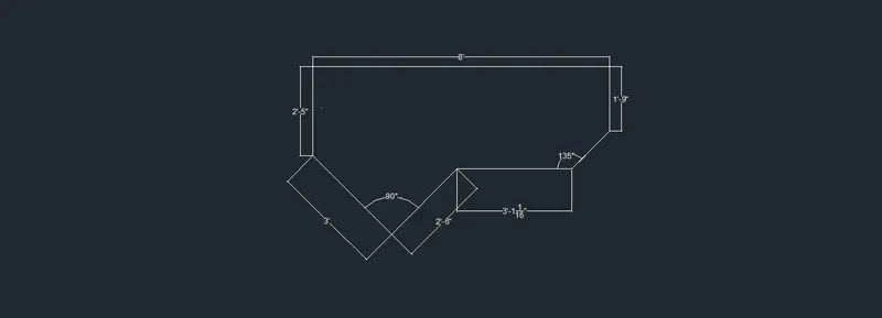
QNS2) TO DRAFT THE FOLLOWING GEOMETRY USING THE ARCHITECTURAL UNIT OF MEASUREMENT:
PROCEDURE :
Type UN and press enter
under drawing units, select the desired unit that is ARCHITECTURAL
type L in the command line and press enter
specify first point :2,5
specify next point:@2'10"<45
specify next point:@0,1'9"
specify next point:@-8'
specify next point:@-2'5:
specify next point:@0,-2.5
switch on polar tracking of 30,60,90
place the curser at 300 degree tracking and type 3'
now place the curser at 30 degree and type2'6"
give the dimension as per the drawing using dimension command from the command bar.
the geometry using architectural units is completed
QNS3)
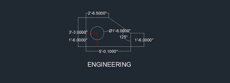
TO DRAFT THE FOLLOWING USING GEOMETRY USING THE ENGINEERING UNIT OF MEASUREMENT:
PROCEDURE :
Type UN and press enter
under drawing units, select the desired unit that is ENGINEERING
type REC in the command line and press enter
specify first point Corner of the rectangle
enter D for dimensions.
enter the lenght:5'0.1"
enter the width:3'3.0"
specify the other corner.
tpe CHA or CHAMFER in the command line and press enter.
specify the start point:d
specify next point:@1'3.0"
specify next point:@1'-6"
type Cin the command line and press enter
specify center point of circle:e
specify diameter of circle:@1'-6"
delet unwanted lines
give the dimension as per the drawing using dimension command from the command bar.
the geomatry using engineering units is completed
QNS4)
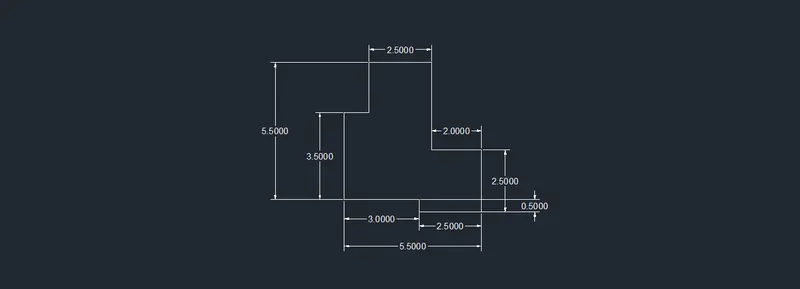
TO DRAW THE FOLLOWING GEOMETRY
PROCEDURE :
Type UN and press enter
under drawing units, select the desired unit that is decimal
type L in the command line and press enter
specify first point :1,1
specify next point:@3,0
specify next point:@0,-5
specify next point:@2.5,0
specify next point:@-2,0
specify next point:@0,3
specify next point:@-2.5,0
specify next point:@0,-2.5
type L in the command line and press enter
specify first point :a
specify next point:@0,3
specify next point:@1,0
Delet unwanted lines
give the dimension as per the drawing using dimension command from the command bar.
the geomatry using Decimal units is completed
QNS5)
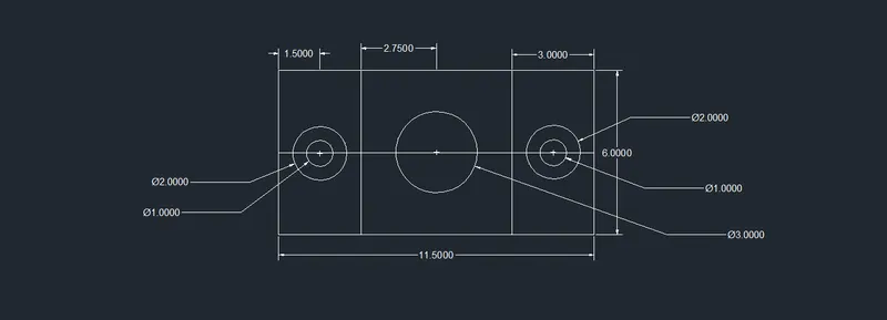
TO DRAFT THE FOLLOWING GEOMETRY:
PROCEDURE :
Type UN and press enter
under drawing units, select the desired unit that is ENGINEERING
type REC in the command line and press enter
specify first point Corner of the rectangle
enter D for dimensions.
enter the lenght:3
enter the width:6
specify the other corner.
type L in the command line and press enter
specify first point :A
specify next point:@1.5,0
specify next point:@0,6
turn on midpoint in object snap
type C and press enter
specify center point of circle:
specify radius of circle:5
type O or OFFSET on the command line and press ENTER
specify the value of offset distance:.5
select the circle to offset and click outside the circle
type REC in the command line and press enter
specify first point Corner of the rectangle
enter D for dimensions.
enter the lenght:5.5
enter the width:6
specify the other corner.
trim and erase the unwanted lines
type CO and press enter
select the rectangle abcd and click D for displacemant and type @8.5,0
specify the base point as a and click enter
trim and erase the unwanted lines
give the dimension as per the drawing using dimension command from the command bar.
the geomatry using Decimal units is completed
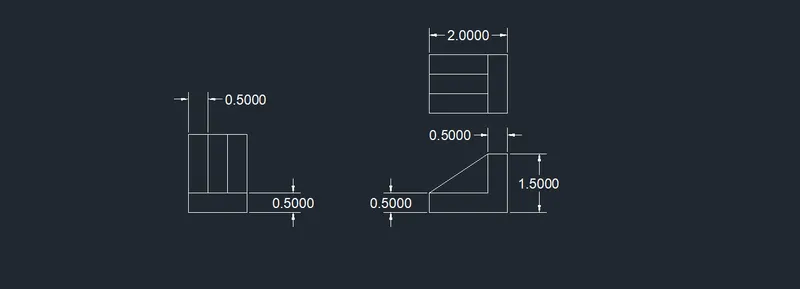
QNS6)
TO DRAFT THE FOLLOWING GEOMETRY:
PROCEDURE :
Type UN and press enter
under drawing units, select the desired unit that decimal
type REC in the command line and press enter
specify first point Corner of the rectangle
enter D for dimensions.
enter the lenght:1.5
enter the width:.5
specify the other corner.
Type REC in the command line and press enter
specify first point Corner of the rectangle as E
enter D for dimensions.
enter the lenght:.5
enter the width:1.5
specify the other corner.
type CO and press enter
select the rectangle EFGH and click D for displacement and type @0,.5
specify the base point as B and click enter
type L in the command line and press enter
specify first point :E
specify next point:@0,-.5
specify next point :1.5,0
specify next point:@0,1.5
specify next point:@-5,0
specify next point:@0,-1
specify next point:@-1,0
type L in the command line and press enter
specify first point :E
specify next point :F
Type REC in the command line and press enter
specify first point Corner of the rectangle as B
enter D for dimensions.
enter the lenght:.5
enter the width:1.5
specify the other corner
Type REC in the command line and press enter
specify first point Corner of the rectangle as E
enter D for dimensions.
enter the lenght:.5
enter the width:1.5
specify the other corner.
type CO and press enter
select the rectangle EFGH and click D for displacement and type @0,.5
specify the base point as B and click enter
give the dimension as per the drawing using dimension command from the command bar.
the geomatry using decimal units is completed
QNS7)
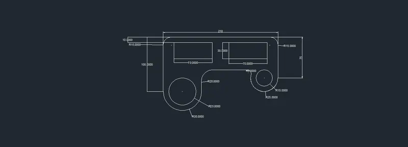
TO DRAFT THE FOLLOEING GEOMETRY:
PROCEDURE :
Type UN and press enter
under drawing units, select the desired unit that is decimal
type L in the command line and press enter
specify first point :L
specify next point:@0,-100
specify next point:@210,0
specify next point:@0,75
TYPE F and press enter
select the first line LO
specify the radius 15
select the second line as ON and press enter
type F and press enter
select the first line MN
specify radius as 15
type L in the command line and press enter
specify first point :L
specify next point:@70,0
type L in the command line and press enter
specify first point :M
specify next point:@-50,0
type C and press enter
specify center point of circle K
specify radius of circle:25
type C and press enter
specify center point of circle j
specify radius of circle:15
from draw panel select start end radius option from arc menu
specify start point as g
specify end [oint as h
radius of arc as 35
from draw panel selct start and radius option from arc menu
specify start point as i
specify end point as h
radius of arc as 25
trim lines fg and hi
by drawing a line 10 units from top 20 units from left side .the points intersecting both will be the start point of rectanfgle
type REC in the command line and press enter
specify first point Corner of the rectangle
enter D for dimensions.
enter the lenght:70
enter the width:.30
specify the other corner.
type CO and press enter
select the rectangle D for the displacement and type @100
specify the base point and click enter
using trim command erase of unwanted lines.
type L in the command line and press enter
specify the strat point E
specify the end point 0,20
now draw a line perpendicular to the above line and draw lines starting from a and d respectively
trim off and erase the unwanted lines.
give the dimension as per the drawing using dimension command from the command bar.
the geomatry using decimal units is completed
QNS8)
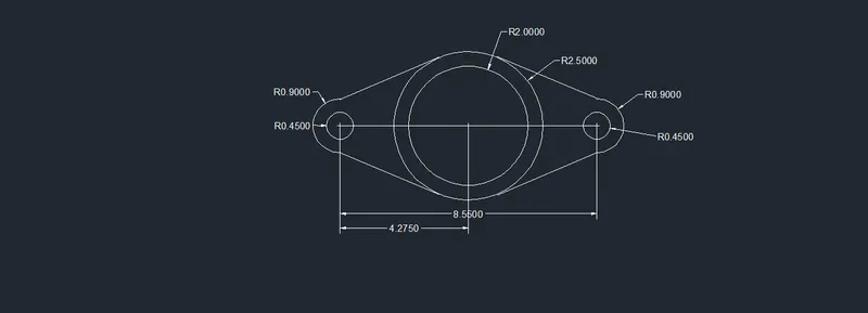
TO DRAFT THE FOLLOWING GEOMETRY:
PROCEDURE :
Type UN and press enter
under drawing units, select the desired unit that is decimal
type Cin the command line and press enter
Specify center point of circle:5,5
specify radius of circle:2
type O or OFFSET on the command line and press enter
specify the value of offset distance.5
select the object to offset and click outside of the circle
type L in the command line and press enter
specify first point :5,5
specify next point:@8.55,0
type O or OFFSET on the command line and press enter
specify the value of offset distance.9
select the object to offset and cllick on top and bottom
close the figure with two lines on both sides
type Cin the command line and press enter
Specify center point of circle :A
specify radius of circle:45
ype Cin the command line and press enter
Specify center point of circle:B
specify radius of circle:45
from draw panel selct start and radius option from arc menu
specify start point as C
specify end point as D
radius of arc as .90
from draw panel selct start and radius option from arc menu
specify start point as E
specify end point as F
radius of arc as .90
give the dimension as per the drawing using dimension command from the command bar.
the geomatry using decimal units is completed
QNS9)
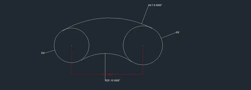
TO DRAFT THE FOLLOWING GEOMETRY:
PROCEDURE :
Type UN and press enter
under drawing units, select the desired unit that is DECIMAL
type L in the command line and press enter
specify first point :5',5"
specify next point:@32'6",0
Type Cin the command line and press enter
Specify center point of circle:5'5"
specify radius of circle:8
ype Cin the command line and press enter
Specify center point of circle:5'5"
specify radius of circle:9
Type C and press enter
select tan,tan, rad
select first tangent by clicking on top tangent of left circle
select second tangent by clicking on top tangent of right circle
specify radius as 41'8"
Type C and press enter
select tan,tan, rad
select first tangent by clicking on top tangent of left circle
select second tangent by clicking on top tangent of right circle
specify radius as20'10"
give the dimension as per the drawing using dimension command from the command bar.
the geomatry using DECIMAL units is completed
QNS 10)
TO DRAFT THE FOLLOWING GEOMETRY
PROCEDURE :
Type UN and press enter
under drawing units, select the desired unit that is decimal
type REC in the command line and press enter
specify first point Corner of the rectangle
enter D for dimensions.
enter the lenght:10
enter the width:.10
specify the other corner.
type O or OFFSET on the command line and press enter
specify the value of offset distance.5
select the object to offset and cllick on top and bottom
close the figure with two lines on both sides
Type RO and press enter
select the object :rectangle
and rotate it by 45 degree by selecting a base point
move the rotated rectangle and place it all the center
trim of the additional lines and finally the geometry is completed
the geometry using decimal units is completed

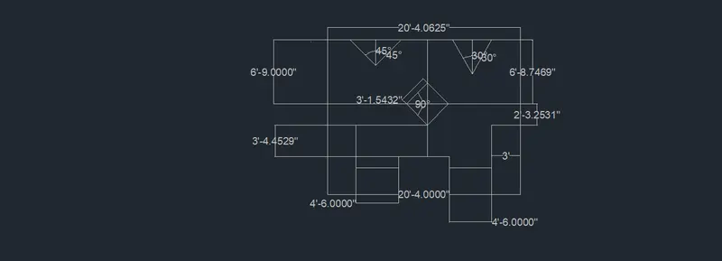
QNS11)
TO DRAFT THE FOLLOWING GEOMETRY
PROCEDURE :
Type UN and press enter
under drawing units, select the desired unit that is ENGINEERING
type L in the command line and press enter
specify first point :G
specify next point:@2'6:,0
specify next point:@0,-1'2"
specify next point:@4'6",0
specify next point:@0,4'6"
specify next point:@3',0
specify next point:@0,9'
TYPE MI AND PRESS ENTER
SELECT THE mirroe object
specify the first point of mirror
specify the second mirror point at top
at erase source object type N
type L in the command line and press enter
specify first point :e
specify next point:@0,3'7"
specify next point:@-8'7",0
turn on the polar tracking for 30,60,90 degree
with d as center draw a line an angle of 30 degree tii it touches the bottom line and 120 d towards up and close the figure at f
type L in the command line and press enter
specify first point :c
specify next point:@0,-2'8"
specify next point:@6'7",0
turn on the polar tracking for 45,90,135 degree
with d as center draw a line an angle of 45 degree tii it touches the bottom line and 135 d towards up and close the figure at c
delete unnessesary line
type REC in the command line and press enter
specify first point Corner of the rectangle
enter D for dimensions.
enter the lenght:3'
enter the width:.3'
specify the other corner
Type RO and press enter
select the object :rectangle
and rotate it by 45 degree by selecting a base point
move the rotated rectangle and place it all the rectangle
place the rectangle created in the correct place using the diagonal line
delet r trim unwanted lines to get the final geomatry
give the dimension as per the drawing using dimension command from the command bar.
the geomatry using engineering units is completed
RESULT:
Drafted various geometries using champer ,fillet ,offset rotate, copy, trim tools