Creating a Floor plan, Footing detail and Isometric view using AutoCad
1....
AIM:
To creating a floor plan ,footing detail and isometric view using AutoCAD
INTRODUCTION:
The main objective of this assignment is to get in touch withh various tools in AutoCAD like the rectangle,polylines, modification tools like copy,move offset and modes like snap mode and orho mode . these tools will be understood by creating a footing detail, two bedroom building, cross section of a 2 bedroom building sowing foundation reference alphabets are provided only when required.
PART 1: CROSS SECTION OF LOAD BEARING WALL OVER SPREAD FOOTING:
THE STEP BY STEP PROCEDURE FOR DRAWING CS OF LOAD BEARING WALL OVER SPREAD FOOTING IS AS FOLLOWS:
PROCEDURE:
*open AutoCAD
*in the command prompt type QNEW
*click on imperial template,advanced setup, decimal
*in the command prompt type UNITS
*type= decimal,precision=0.00,angle=decimal degree
*in the command prompt type DS
*snap spacing (x and y spacing=0.5)
*grid spacing (x and y spacing=0.5)
*in the command prompt type rec(RECTANGLE)
*first corner point 1,1
*in command prompt click dimensions
*specify length of the rectangle0.90
*specify width of the rectangle0.25
*in the command prompt click rec(RECTANGLE)
* specify first corner point 1.2 , 1.25
**in the command prompt click dimensions
*specify length of the rectangle0.50
*specify width of the rectangle0.40
*in the command prompt click rec(RECTANGLE)
* specify first corner point 1.2 , 1.65
*in the command prompt click dimensions
*specify length of the rectangle0.40
*specify width of the rectangle0.40
*in the command prompt click rec(RECTANGLE)
* specify first corner point 1.30 , 2.05
*in the command prompt click dimensions
*specify length of the rectangle0.30
*specify width of the rectangle0.60
*in the command prompt click rec(RECTANGLE)
* specify first corner point 1.30 , 2.65
*in the command prompt click dimensions
*specify length of the rectangle0.30
*specify width of the rectangle0.05
*in the command prompt click rec(RECTANGLE)
* specify first corner point 1.30 , 2.7
*in the command prompt click dimensions
*specify length of the rectangle0.30
*specify width of the rectangle1.0
*in the command prompt click rec(RECTANGLE)
* specify first corner point 1.25 , 2.05
*in the command prompt click dimensions
*specify length of the rectangle1.15
*specify width of the rectangle0.15
*in the command prompt type line
* specify first corner point 0.4 , 2.05
*in the command prompt type0.15<90
*in the command prompt type0.3<0
*in the command prompt type0.15<90
*in the command prompt type0.3<0
*in the command prompt type0.15<90
*in the command prompt type0.3<0
RESULT:
C.S , OF load bearing wall over spread footing

2.
AIM:
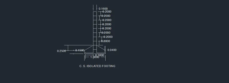
TO DRAW C.S ISLATED FOOTING USING AUTOCAD SOFTWARE
PROCEDURE:
*open AutoCAD
*in the command prompt type QNEW
*click on imperial template,advanced setup, decimal
*in the command prompt type UNITS
*type= decimal,precision=0.00,angle=decimal degree
*in the command prompt type DS
*snap spacing (x and y spacing=0.5)
*grid spacing (x and y spacing=0.5)
*in the command prompt type line
*in the command prompt specify start point 1,1
*in the command prompt type @1<0
*in the command prompt type @0.15<90
*in the command prompt type line
*in the command prompt type @0.04,1.04
*in the command prompt type @0.38<0
*in the command prompt type @1.96<90
*in the command prompt type @0.17<0
*in the command prompt type @0.96<270
*in the command prompt type @0.38<0
*in the command prompt type @0.05<90
*in the command prompt type line
*in the command prompt type 1.04,1.04
*in the command prompt type @0.05<90
*in the command prompt type line
*in the command prompt specify start point 1.42,3.00
*in the command prompt type @0.04<180
*in the command prompt type 1.60<270
* join coordinate points (1.38,1.40) and (1,1.15) using line command
*in the command prompt specify start point 1.59,3.00
*in the command prompt type @0.04<0
*in the command prompt type 1.60<270
* join coordinate points (1.63,1.40) and (2,1.15) using line command
* click on the line in which coordinate points are (1.42,3) and(1.59,3)
*in the command prompt type offset
*in the command prompt type odistance0.20
*in the command prompt type multiple( click on the objects till you get the number)
RESULT:
C.S ISOLATED FOOTING
3.
AIM
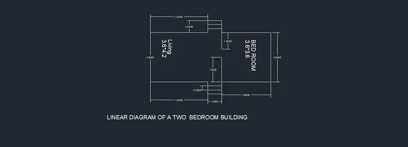
TO draw a line diagram of a two bedroom building:
PROCEDURE:
*open AutoCAD
*in the command prompt type QNEW
*click on imperial template,advanced setup, decimal
*in the command prompt type UNITS
*type= decimal,precision=0.00,angle=decimal degree
*in the command prompt type DS
*snap spacing (x and y spacing=0.5)
*grid spacing (x and y spacing=0.5)
*in the command prompt type line
*in the command prompt specify start point 1,1
*in the command prompt type @3.6<0
*in the command prompt type @0.90<270
*in the command prompt type @1<0
*in the command prompt type @0.9<90
*in the command prompt type @4.2<0
*in the command prompt type @3.60<90
*in the command prompt type @4.2<180
*in the command prompt type @0.09<90
*in the command prompt type @1<180
*in the command prompt type 1.09<270
*in the command prompt type @3.60<180
*in the command prompt click close
*in the command prompt type line
*in the command prompt specify first point 4.60,1
*in the command prompt type @1.80<270
*in the command prompt type line
*in the command prompt specify first point 4.60,4.60
*in the command prompt type 1.80<270
*in the command prompt type offset
*in the command prompt type 0.30
*click on the line in which coordinate points are (4.60,0.10)and(5.60,0.10)
click on the previous line to get segments
*click on the line in which coordinate points are (4.60,5.50)and(5.60,0.50)
click on the previous line to get segments
RESULTS:
line diagram of a two bedroom building
4.
AIM
To draw c.s of load bearing wall showing foundation details:
PROCEDURE:
*open AutoCAD
*in the command prompt type QNEW
*click on imperial template,advanced setup, decimal
*in the command prompt type UNITS
*type= decimal,precision=0.00,angle=decimal degree
*in the command prompt type DS
*snap spacing (x and y spacing=0.5)
*grid spacing (x and y spacing=0.5)
*in the command prompt type rec(RECTANGLE)
*first corner point 1,1
*in command prompt click dimensions
*specify length of the rectangle0.90
*specify width of the rectangle0.45
*in the command prompt click rec(RECTANGLE)
* specify first corner point 1.15 , 1.45
**in the command prompt click dimensions
*specify length of the rectangle0.60
*specify width of the rectangle0.40
*in the command prompt click rec(RECTANGLE)
* specify first corner point 1.2 , 1.85
*in the command prompt click dimensions
*specify length of the rectangle0.50
*specify width of the rectangle0.30
*in the command prompt click rec(RECTANGLE)
* specify first corner point 1.25 , 2.15
*in the command prompt click dimensions
*specify length of the rectangle0.40
*specify width of the rectangle0.60
*in the command prompt click rec(RECTANGLE)
* specify first corner point 1.30 , 2.75
*in the command prompt click dimensions
*specify length of the rectangle0.30
*specify width of the rectangle1.00
RESULT:
C.S OF LOAD BEARING WALL SHOWING FOUNDATION DETAILS:

6.
AIM:
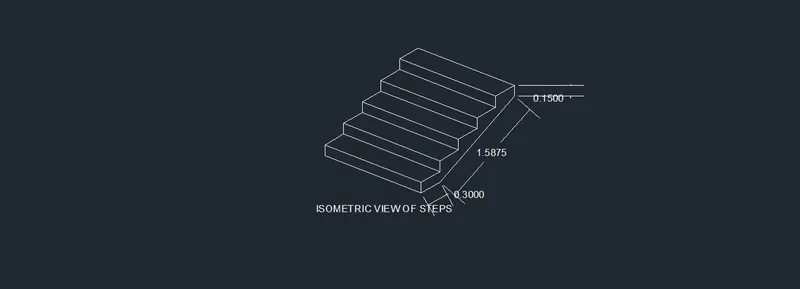
To draw isometric view of steps using Autocad
PROCEDURE:
*open AutoCAD
*in the command prompt type QNEW
*click on imperial template,advanced setup, decimal
*in the command prompt type UNITS
*type= decimal,precision=0.00,angle=decimal degree
*in the command prompt type DS
*in drafting setting (ds)off"snap on" and off" grid on"
*select on isometric snap
*keep ortho(f8) on
*in the comand prompt type line
*specify the point r select a point
* in the command prompt type1( distance)
* press f5 to get the line in decimal direction
* in the command prompt type0.15( distance)
* press f5 to get the line in decimal direction
* in the command prompt type0.30( distance)
* press f5 to get the line in decimal direction
these process is done till the steps are formed
RESULT:
ISOMETRIC VIEW OF STEPS:
8.
AIM:
To draw isometric view of steps using Autocad
PROCEDURE:
*open AutoCAD
*in the command prompt type QNEW
*click on imperial template,advanced setup, decimal
*in the command prompt type UNITS
*type= decimal,precision=0.00,angle=decimal degree
*in the command prompt type DS
*in drafting setting (ds)off"snap on" and off" grid on"
*select on isometric snap
*keep ortho(f8) on
*in the comand prompt type line
*specify the point r select a point
* press f5 to get the line in decimal direction
* in the command prompt type the required distance
these process is done till the steps are formed
RESULT:
ISOMETRIC VIEW OF GLABLE WALL: