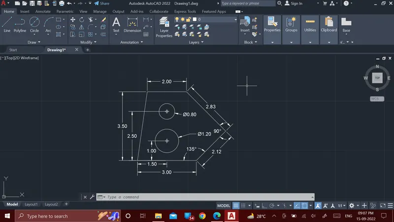
Drafting of various geometries using Chamfer, Fillet tool in AutoCad
Aim: To draw the figure 1 with the unit taken as a decimal.
Introduction: The AutoCAD Command line is like a combined control panel and index of all AutoCAD commands you run – and have run – on your drawing.
Procedure:
- first take a line of 3unit
- then take a line 2.12unit with an angle 45
- then take a line 2.83unit with an angle 135
- then take 2unit at 0'
- then close the figure
- after that select break command and break the line 3unit at its mid-point
- then draw a line with 2.5unit
- then select offset and make a line 1unit distance from 2unit line and 3unit line
- and draw two circles with a diameter of 1.2 and 0.8unit like in the figure
result:
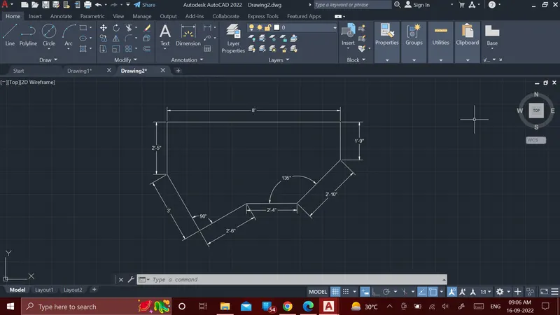
Aim: To draw the figure 2 with the unit taken as Architectural.
Introduction: The AutoCAD Command line is like a combined control panel and index of all AutoCAD commands you run – and have run – on your drawing.
Procedure:
- first take a line 8' then take 1'9" and 2'5" in the two-end point
- then take 3'<60 from the line2'5"
- then take 2'6"<30
- take 2'10"<225 from the line 1'9"
- then close the figure
result:
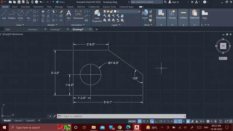
Aim: To draw the figure 3 with the unit taken as a engineering.
Introduction: The AutoCAD Command line is like a combined control panel and index of all AutoCAD commands you run – and have run – on your drawing.
Procedure:
- first take a line with 2'6.5" and start the line form right to left
- then take a line 3'3"<270
- then take a line1'3"<0 then continue with 4'2.9"
- then take a line 1'6"
- the close figure
- then make a straight line from 1'6" at an angle <0
- then draw a line from 1'3" at a<90
- then draw a circle at the intersect point with a diameter 1'6"
result:
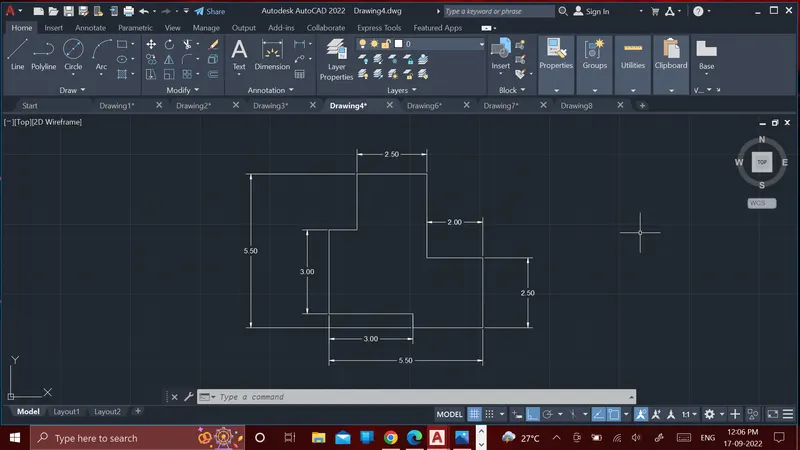
Aim: To draw the figure 4 with the unit taken as a decimal
Introduction: The AutoCAD Command line is like a combined control panel and index of all AutoCAD commands you run – and have run – on your drawing.
Procedure:
- take a line 2.5unit
- take a line 2unit <270
- take a line 1unit<180
- take a line 3unit<270
- take a line 3unit<0
- take a line 0.5unit<270
- take a line 2.5unit<0
- take a line 2.5unit<90
- take a line 2unit<180
- close
Result:
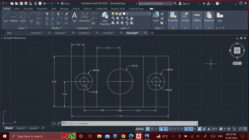
Aim: To draw the figure 5 with the unit taken as decimal
Introduction: The AutoCAD Command line is like a combined control panel and index of all AutoCAD commands you run – and have run – on your drawing.
Procedure:
- make rectangle by using line command with length 11.5unit and width 6unit
- take the break the line 11.5 at its mid-point
- make two offset lines of 6unit at a distance of 1.5
- then again break the line at its mid-point of these two lines
- and make an offset of 3unit from 11.5 unit
- then joint all the mid-point and make three intersect point and draw three circles with diameter 3,2,1unit
- and then trim the extra line and complete the figure
result:
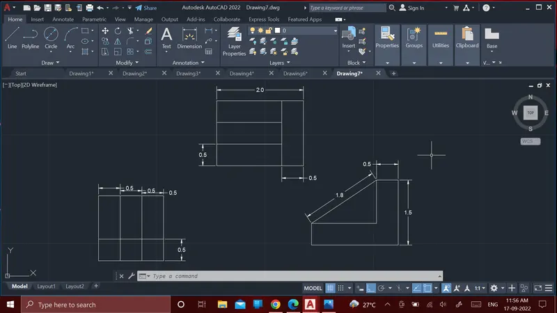
Aim: To draw the figure 6 with the unit taken as a decimal
Introduction: The AutoCAD Command line is like a combined control panel and index of all AutoCAD commands you run – and have run – on your drawing.
Procedure:
- make three figures with 3unit as a baseline
- and make the sideline with a 1.5unit
- and use the offset distance with a 0.5unit in the three figure
- and complete the figure
result:
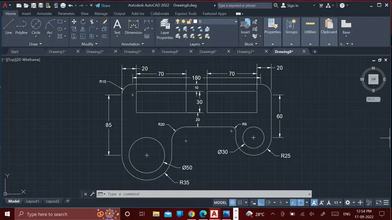
Aim: To draw the figure 7 with the unit taken as a decimal
Introduction: The AutoCAD Command line is like a combined control panel and index of all AutoCAD commands you run – and have run – on your drawing.
Procedure:
- make a line 210 unit<180
- then make a line 100 unit<270
- then make a line 75 unit<0
- then make a line 40unit<90
- then make a line 75unit<270 from 210unit
- then make a line 50unit<180
- then make 15unit <90
- then close
- then make offset of 20unit from the two sidelines and make 10unit from top side and 20unit from down
- then select trim command and trim the extra line to make a rectangle
- after that select arc command
- then select the line 75unit and make radius 35unit
- and make another radius of 25unit on the line 50unit
- then select fillet command and make a radius of 20unit and 6unit in the down and radius 15 in the top of the figure
result:
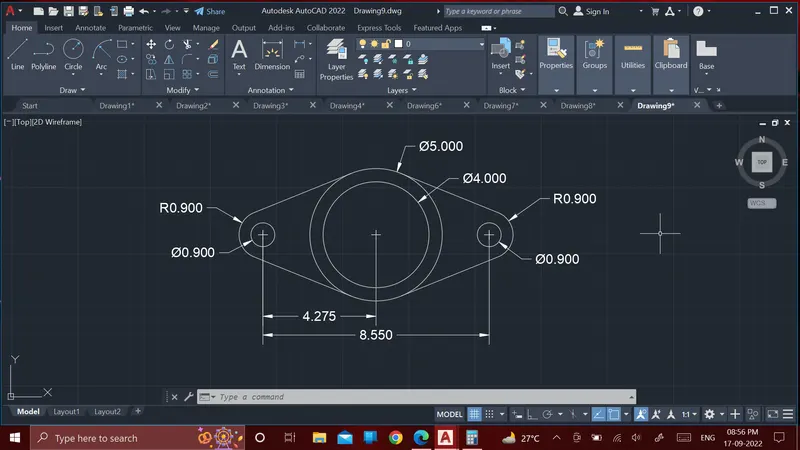
Aim: To draw the figure 8 with the unit taken as a decimal
Introduction: The AutoCAD Command line is like a combined control panel and index of all AutoCAD commands you run – and have run – on your drawing. The circle command is used to draw a circle by specifying the center point and radius.
Procedure:
- make a line with 8.55 unit
- select circle command and make two 2 circles with the diameter 5 & 4 unit in the mid-point
- make two circles at the end-point with the radius of 0.9 and 0.9 diameter similar to another end side
- open the object snap menu select tangent and close all the menu
- then make the lines with help of the tangent and close the figure
- then select trim command and trim the extra line to complete the figure
result:
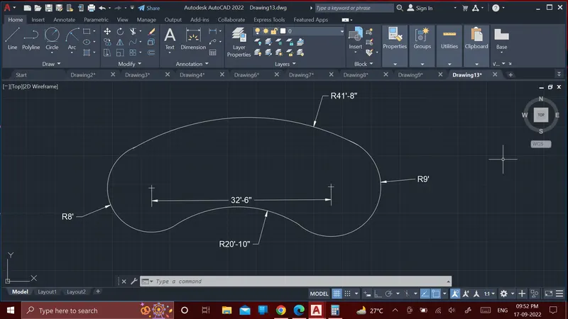
Aim: To draw the figure 9 with the unit taken as an architectural
Introduction: The AutoCAD Command line is like a combined control panel and index of all AutoCAD commands you run – and have run – on your drawing. The circle command is used to draw a circle by specifying the center point and radius.
Procedure:
- make two circles with radius 8' & 9' at a distance of 32'6"
- then select the tangent-tangent-radius
- make two circles at top and bottom with the radius 20'10' & 41'8'
- then select the move command and adjust the side to complete the figure
- then select the trim command and trim the extra lines
result:
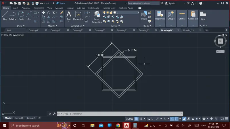
Aim: To draw the figure 10 with the unit taken as a decimal
Introduction: The AutoCAD Command line is like a combined control panel and index of all AutoCAD commands you run – and have run – on your drawing.
Procedure:
- make two rectangles with 3 & 3 unit in all the side
- the rotate one rectangle and move to the mid with help of the geometric center in object snap menu
- then select offset menu make distance of 0.1174 thickness of rectangle
- then select the trim command and trim the extra lines to complete the figure
result:
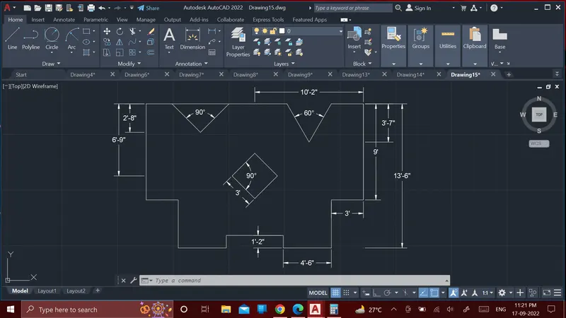
Aim: To draw the figure 11 with the unit taken as an architectural
Introduction: The AutoCAD Command line is like a combined control panel and index of all AutoCAD commands you run – and have run – on your drawing.
Procedure:
- make line with 20'4"
- make two lines from the two side lines with 9' and 9' which shown in the figure
- make two lines from the end point with 3'<180, 3'<0
- make two lines from the end point with 4'6"<270
- make two lines from the end point with 4'6"<180, 4'6"<0
- make two lines from the end point with 1'2"<90
- then close the figure
- then select break command and break the top line in its mid-point
- then draw an offset at a distance 6'9" which show in the figure
- then make a rectangle with 3',3'unit and rotate it to move the intersect point in the middle of the figure
- make two offset lines at a distance of 2'8" & 3'7"
- then again break the two lines in the top from its mid-point and draw a perpendicular from the mid-point
- select the polar tracking and change the degree to 30,60,90 and draw the line at a <30
- select the polar tracking and change the degree to 45,90,135 and draw the line at a <45
- then trim the remaining lines to complete the figure
result: