Creating a Floor plan, Footing detail and Isometric view using AutoCad
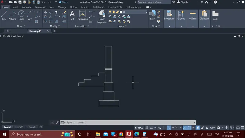
Aim: To draw the figure of C.S of load bearing wall over spread footing.
Introduction: The AutoCAD Command line is like a combined control panel and index of all AutoCAD commands you run – and have run – on your drawing.
Procedure:
- take any point and draw a line with 0.9-unit length (orthomode on)
- then take 0.25unit width
- then take 0.4unit at <180
- then take 0.4unit at <90
- then take 0.1unit at <180
- then its similar taken 0.4<90, 0.1<108, 0.6<90,0.05<90,1<90,0.3<180,1<270, 0.05<270,0.6<270,
- previous end point 0.15<270,0.3<180,0.15<270,0.3<180,0.15<270,0.3<180,0.15<270,0.3<180,0.15<270,0.3<180,0.15<270,1.15<0,0.25<270,0.1<180,0.4<270,0.4<180, close.
Result:
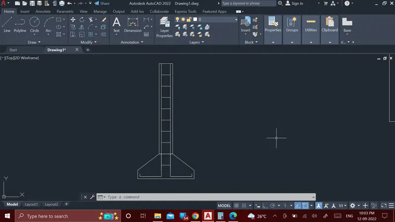
Aim: To draw the figure of C.S ISOLATED FOOTING
Introduction: The AutoCAD Command line is like a combined control panel and index of all AutoCAD commands you run – and have run – on your drawing.
Procedure:
- Type line command and take 1.6<270 take 0.38<180,0.44<270,1<0
- take chamfer then type distance take the first point 0.38 and second point 0.25
- use offset tool on the line 1.6 length and move toward inside 0.04, again use offset tool on 1.6 and move toward inside 0.2unit, again use offset tool on 0.2 line and move 0.04unit inside
- use offset tool on chamfer line and move in opposite side 0.24
- on the top join the line and take the middle line and offset tool 0.2unit and move downward 9 step
- at the end of the 0.44 line draw a line 1<0
- use offset tool on line 1unitand move inside with 0.04unit
- close the remaining figure and trim the remaining figure to make the total figure
Result:
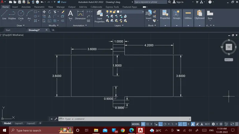
Aim: To draw the figure of line diagram of a two-bedroom building
Introduction: The AutoCAD Command line is like a combined control panel and index of all AutoCAD commands you run – and have run – on your drawing.
Procedure:
- take the rectangle and take length and width 3.6 unit and trim the inside part
- take the end point from the trim side and draw a line 0.9<270, 1<0,0.9<90, 4.2<0,3.6<90,4.2<180,0.9<90,1<180,0.9<270,1.8<270
- take offset and select 1unit line in the top and down and draw 0.3unit inside 2 steps
- take the line 3.6unit down and draw a line 0.9<90
Result:
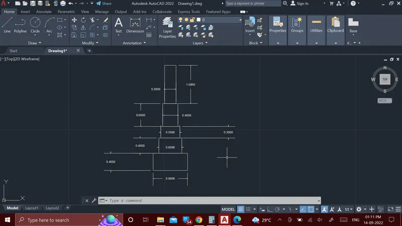
Aim: To draw the figure C.S of load bearing wall showing foundation details
Introduction: The AutoCAD Command rectangle is like a combined control panel and index of all AutoCAD commands you run – and have run – on your drawing.
Procedure:
- draw 5 rectangles with length and width 0.9*0.45,0.6*0.4,0.5*0.3,0.4*0.6&0.3*1.0
- and joint the 5 rectangles with the help of the midpoint according to the figure
Result:
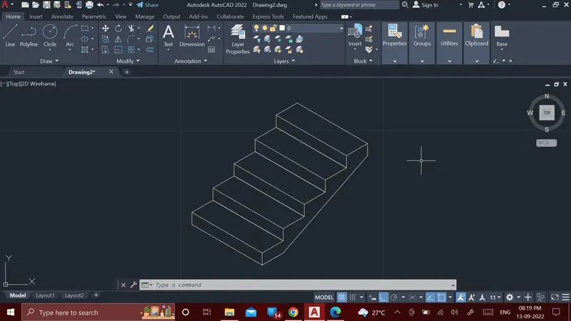
Aim: To draw the figure isometric view of steps
Introduction: An AutoCAD isometric drawing is a 2-dimensional drawing just like a paper drawing.
Procedure:
- select isometric drafting and toggle with F5 and also on the orthomode
- isoplane top 1unit<330 then isoplane top 0.3unit<210 and close
- change to isoplane left take the end point of 1unit and draw downward 0.15unit, 1unit,0.15unit top and close the figure
- then copy 4 time the figure and close the figure with a line
Result:
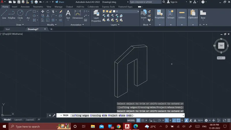
Aim: To draw the figure isometric view of gable wall
Introduction: An AutoCAD isometric drawing is a 2-dimensional drawing just like a paper drawing.
Procedure:
- take isoplane left and on the orthomode
- isoplane left0.3unit and downward 3unit then take the end point and draw a downward 3unit and close
- take the end point in the down side and change the marker to isoplane top and move 1unit
- then change to isoplane right and move up 2.42unit then move left side 1unit and move downward 2.42unit
- move right side 1unit, move top 3unit
- end point in right side 1unit take isoplane left 0.3 then move top 3.25
take the point of the line 3unit from both top side and join all the line and make the thickness 0.3 from the endpoint of 3.25 line
- and trim the extra part to complete the drawing
Result: