Drafting of various geometries using Chamfer, Fillet tool in AutoCad
AIM: Draftng of various geometries usig Chamfer, fillet tools in autocad
- Decimals
- Architectural
- Engineerings and few more
Introduction:
- Drawing the drawings in actucad by using various tools like Draw Tools, Modify tools and with dimensions in linear and angular and aligined and with help of object snap to specify the points
- Commends used Line, Circle, offset, Chanfer, Fillet, Trim, Extand, Move, Copy, Mirror, Break and few more.
Procedure:
Decimals
Step-1
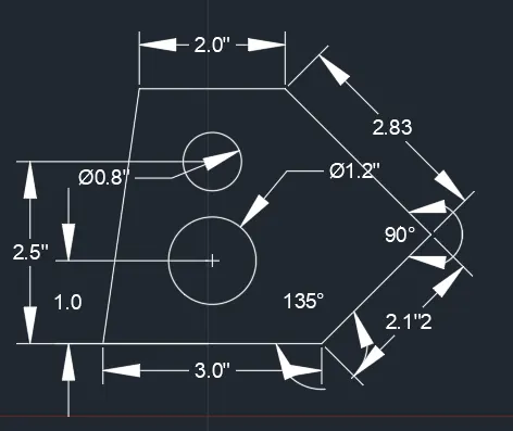
- Use the line command by using L enter
- Specify the first point (1,1)
- Specify the next point (<45, 2.12) towards NE direction
- Specify the next point (<135,2.83) towards NW direction
- Specify the next point (2.0) use the cursor towards W direction
- Close the command by using C enter to close the drawing to first point.

Step-2
- Use the line command by using L enter
- Specify the first point (2.5,1)
- Draw a referance line towards the N direction by using cursor and the distance of 2.5 and use escape to close the command
- Use the break command by using BR enter
- Specify the first point 1 enter to break the line into 2 lines with distance of 1 and 1.5
- Use the circle command by using C enter
- specify the point of end of the refernce line first breaked line
- Draw circle with D enter to change the radius to diameter and 1.2 enter
- Use the circle command by using C enter
- specify the point of end of the refernce line second break line
- Draw circle with D enter to change the radius to diameter and 0.2 enter
- And erase the noth reference lines by using E enter

Architectural
Step-1
- Chane the units to Decimals to Architrectural
- Use the command by using UN enter
- A Dailog box open and the change type to decimals to architrectural and precision to 0' 0 1/2" and unit scale insented to Inches
- Click on Ok
Step-2
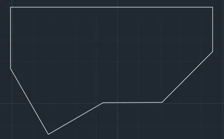
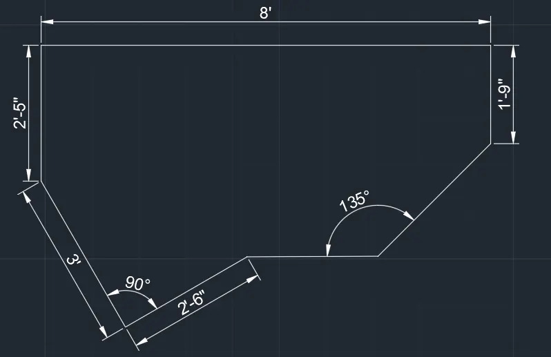
- Use line command ny using L enter
- Specify the first point (0,0)
- Specify the next point towards NE direction by using cursor of 45 degress at a distance of 2'10"
- Specify the next point towards N direction by using cursor of 90 degress at a distance of 1'9"
- Specify the next point towards W direction by using cursor of 180 degress at a distance of 8'
- Specify the next point towards S direction by using cursor of 270 degress at a distance of 2'5"
- Specify the next point towards SE direction by using cursor of 300 degress at a distance of 3'
- Specify the next point towards NE direction by using cursor of 30 degress at a distance of 2'6"
- Close the command by using C enter to close the drawing
Engineering
Step-1
- Chane the units to Decimals to engineering
- Use the command by using UN enter
- A Dailog box open and the change type to decimals to engineering and precision to 0' 0" and unit scale insented to Inches
- Click on Ok
Step-2
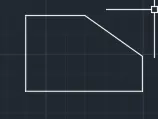
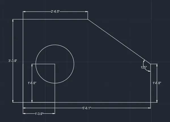
- Use the line command by using L enter
- Specify the first point (10',10')
- Specify the next point towards W direction at a distance of 2'6.5"
- Specify the next point towards S direction at a distance of 3'3"
- Specify the next point towards E direction at a distance of 5'0.1"
- Specify the next point towards N direction at a distance of 1'6"
- Close the command by using c enter to close to first point
Step-2
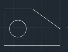
- Use the Circle command by using C enter
- Specify the first point (8'8.5",8'3") and D enter for change radius to diameter
- With diameter of 1'6" and close the command by using escape
Drawing-4
Step-1
- Open the new drawing file
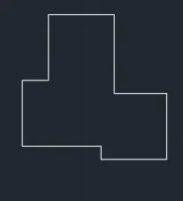
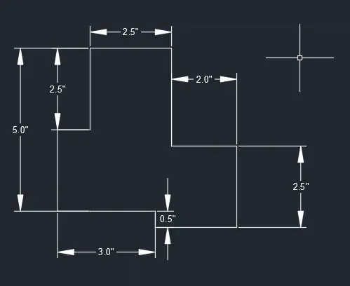
- Use the line command by using L enter
- Specify the first point (1,1)
- Specify the next point 3.0 towards E direction with the help of cursor
- Specify the next point 0.50 towards 5 direction with the help of cursor
- Specify the next point 2.50 towards E direction with the help of cursor
- Specify the next point 2.50 towards N direction with the help of cursor
- Specify the next point 2.0 towards W direction with the help of cursor
- Specify the next point 2.0 towards S direction with the help of cursor
- Specify the next point 1.0 towards W direction with the help of cursor
- Close the command by usinf c Enter to end the drawing
Drawing- 5
Step-1
- Open the new drawing
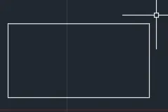
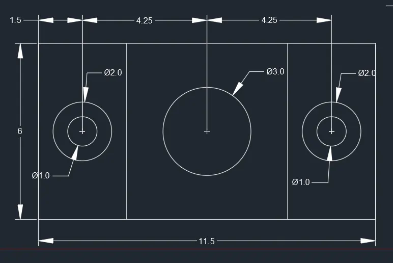
- Use the rectangle command by using REC enter
- Specify the first point (1,1)
- Specify the next point (11.5,6) and enter
Step-2
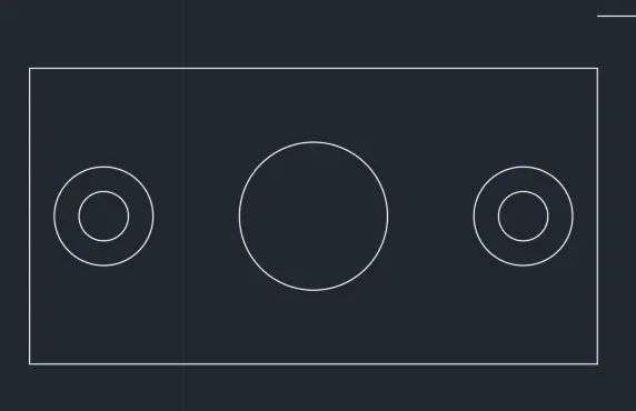
- Use the circle command by using C enter
- Select the center point of the circle draw a circle with daimeter 3 and enter
- Draw a toe refernece lines towards the E and W direction from the center of the circle with 4.5 distance at both sides and close the command by using escape
- Use the circle comand by C enter for the endpoint of the both refernce lines with diameter of 2 and use cmmand again for inner circler 1 at both sides and enter
Step-3
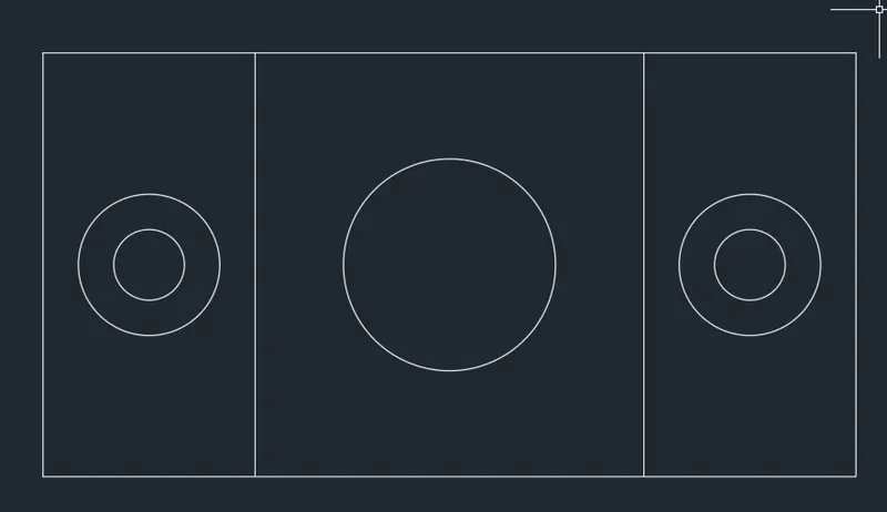
- Explode the rectangle by using command X enter and the object with cursor and enter
- Use the offset command O enter for both vertical lines in rectangle towards E direction and West direction and enter
Drawing-6
Step-1
- Open new autocad drawing
- Use the rectangle command by using REC enter
- Specify the first point (1,1)
- Sepcify next point (1.5,1.5) and enter
- Explode the rectangle by using X enter and slecet the object by using cursor
- Use the offset command by using O enter
- and select the first verticle line the and select do offset at a distance of 1.5 towatds E direction
- and select the second verticle line the and select do offset at a distance of 1.5 towatds W direction
- And select the bottom horizontal line and offset at a distance of 1.5 towards N direction
- And trim the bottom unwanted ines by using TR double enter
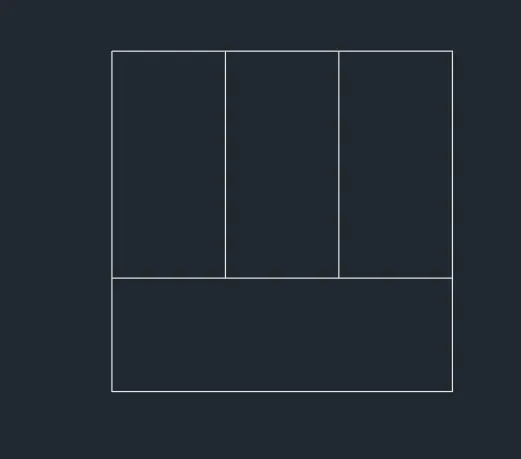
Step-2
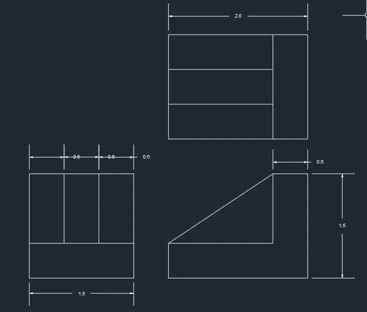
- Use the line command by using L enter
- Specify the first point (3,1)
- Spceify next point 2.0 towards E direction using cursor
- Specify next point 2.0 towards N direction using cursor
- Specify next point 0.5 towards E direction using cursor
- Specify next point 1.0 towards S direction using cursor
- Specify next point 1.5 towards E direction using cursor
- Close the command by using C enter

Step-3
- Use the rectangle command by using REC enter
- Specify the first point (3,3)
- Sepcify next point (2.0,1.5) and enter
- Explode the rectangle by using X enter and slecet the object by using cursor
- And select the bottom horizontal line and offset at a distance of 1.5 towards N direction
- And select the top horizontal line and offset at a distance of 1.5 towards S direction
- and select the second verticle line the and select do offset at a distance of 1.5 towatds W direction
- And the trim the unwanted line by using TR double enter
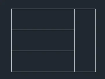
Drawing-7
Step-1
- Open the new cad file
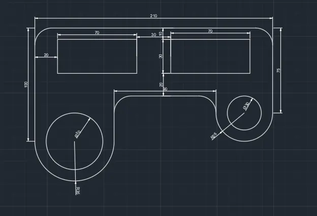
- Use the circle commandd by using C enter
- With a Radius of 35 and enter
- Use the circle command by using C enter
- With a diamter of 50 at the center of the exsisting circle and enter
- Use the line command by using L enter
- Select the east quadrant of 35 Radius circle and draw the line towards 90 degress at a distance of 40
- Specify the next point towards E direction by using cursor at a distance of 90
- Specify the next point towards S direction by using cursor at a distance of 15
- Specify the next point towards E direction by using cursor at a distance of 50
- Specify the next point towards N direction by using cursor at a distance of 75
- Specify the next point towards W direction by using cursor at a distance of 210
- Specify the next point towards S direction by using cursor at a distance of 100
- And the line joints to W quadrant to 35 Radius circle and close the command by using escape
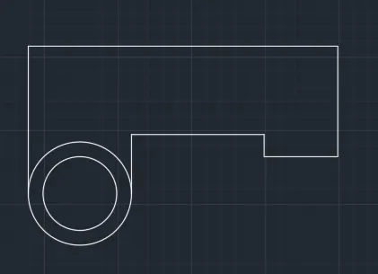
Step-2
- Use the Arc command by using in Ribbon tool-arc-Start end radius
- Select the end point of Right side Horizontal line
- Slect the start point and end point with a radius of 25 and enter
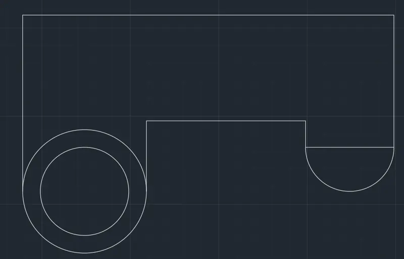
Step-3
- Use the circle command by using C enter
- Select the mid point of Right side Horizontal line
- Draw a circle with a diamter of 30 and enter and erase the that line ny using e enter
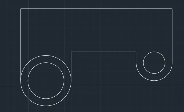
Step-4
- Use the fillet command by using F Enter
- Selct the first line 100 length line and 15 Radius and select the 210 length line and enter
- Selct the first line 75 length line and 15 Radius and select the 210 length line and enter
- Selct the first line 40 length line and 20 Radius and select the 90 length line and enter
- Selct the first line 15 length line and 6 Radius and select the 90 length line and enter
- And trim the unwanted line by using TR enter and crosssing
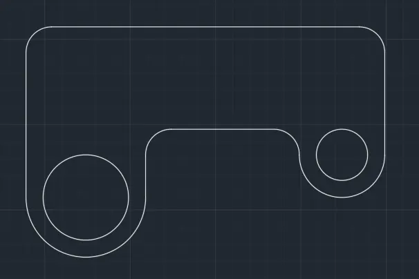
Step-5
- Use the rectangle command by using REC enter
- select the drawing are at any point and with dimension of (70,30)
- Use the line command by using L enter
- Specify the first point as mid point of E direction 30 length line and draw towards E direction by using cursor at a distance of 15
- Specify the second point towards N direction by using cursor at a distance of 25 and enter
- Use the Move command by using M enter and the rectangle object and base point as 25 length end point
- And move to the mid point of the 210 length line
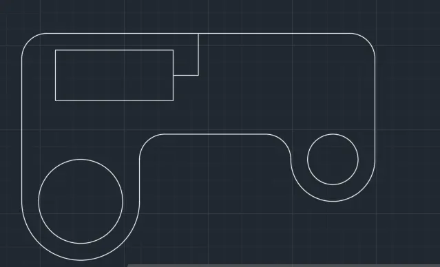
Step-6
- Erase the lines of 15 and 25 length lines by using E enter
- Use the mirror command by using MI enter and the select the rectangle AND ENTER
- Select the mid point of the 210 length line a towards N or S direction by using Cursor and enter No enter
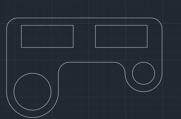
Drawing-8
Step-1
- Open the new cad drawing file
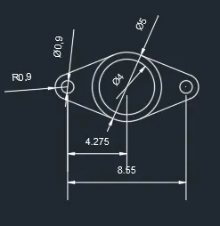
- Use the circle command by using C enter
- Specify the first point (0,0)
- Specify the next point wth diamter of 4 and enter
- Use the circle command by using C enter
- Specify the center point of the existing circle and diamter of 5 and enter

Step-2
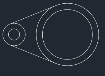
- Use the line command by usng L enter
- From the center of the circle towards W Direction with a distance of 4.275 enter
- Use the circle command by using C enter
- Select the end point of the and diameter of 0.9 and enter
- Select the end point of the and Radius of 0.9 and enter
- Use the object snap and on the tangent
- use the line L enter and joint to right side circle to center circle top and enter
- use the line L enter and joint to right side circle to center circle bottom and enter
Step-3
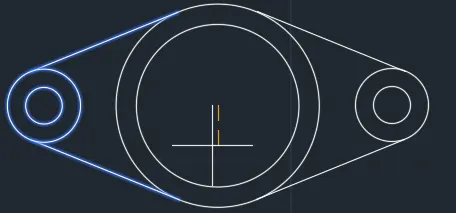
- Use the mirror command by using MI enter
- Select the right side circle and tangent lines and enter
- Specify the center of the 4 diameter circle and to towards N or S direction and enter and No enter
Step-4
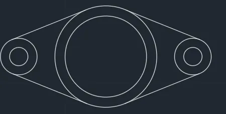
- Use the TRIM ny using TR enter and crossing enter
- trim the unwanted lines
Drawing-9
Step-1
- Chane the units to Decimals to engineering
- Use the command by using UN enter
- A Dailog box open and the change type to decimals to engineering and precision to 0' 0" and unit scale insented to Inches
- Click on Ok
Step-2
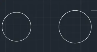
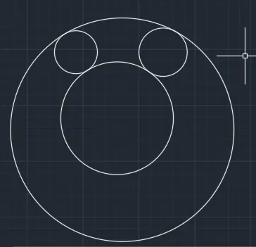
- Use the circle command by using C enter
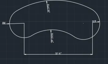
- Specify the first point (0,0) and R8' and enter
- Use the osnap and center of the circle draw a refernce line by usibg L enter towards E direction at a distance of 32'6" and enter
- Use the circle command by using C enter
- Take the end point of the reference line draw circle at R9' and enter
- And erase the refernce line by using E enter
Step-3
- Use the command c enter and ttr enter (for tan tan radius)
- Specify the first tangent circle SE point
- Specify the second tangent circle SE point
- Sepcify the radius of the 20' 10" and enter
- Use the command c enter and ttr enter (for tan tan radius)
- Specify the first tangent circle NW point
- Specify the second tangent circle NE point
- Sepcify the radius of the 41'8" and enter
Step-4
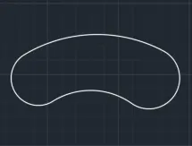
- Use the trim to trim the crossing line
- By using TR enter and crossing enter
Drawing-10
Step-1
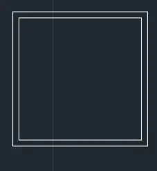
- Use the rectangle command by using REC enter
- Specify the first point (1,1)
- Specify the second point (4,4) (so i am asuming) and enter
- Use the off set command with 0.2 in through and select the object to outerface and close
Step-2
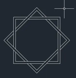
- Use the rotate command by using RO Enter
- and select the object and use specify the center of the object
- And C enter copy command to place another object by rotating one at an agngle of 225 degrees
- And use trim command by using TR enter and in crossing and delete the remaining unwanted lines.
Drawing-11
Step-1
- Open new drawing file
- Chane the units to Decimals to engineering
- Use the command by using UN enter
- A Dailog box open and the change type to decimals to engineering and precision to 0' 0" and unit scale insented to Inches
- Click on Ok
Step-2
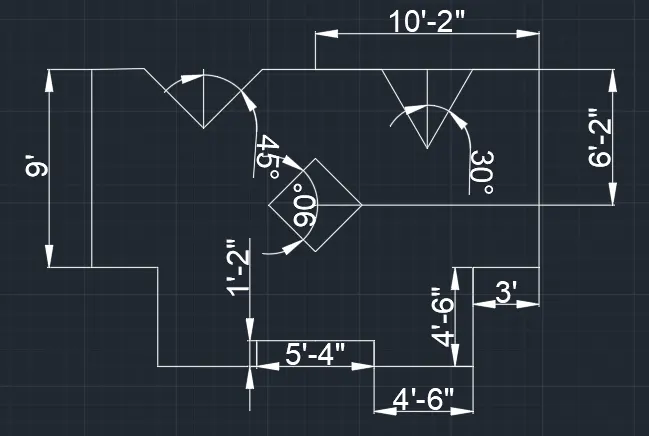
- Use line command by using L enter
- Specify the first point (0,0) origin
- Specify the next point towards S direction by using cursor at a distance of 9'
- Specify the next point towards E direction by using cursor at a distance of 3'
- Specify the next point towards S direction by using cursor at a distance of 4'6"
- Specify the next point towards E direction by using cursor at a distance of 4'6"
- Specify the next point towards N direction by using cursor at a distance of 1'2"
- Specify the next point towards E direction by using cursor at a distance of 5'4"
- Specify the next point towards S direction by using cursor at a distance of 1'2"
- Specify the next point towards E direction by using cursor at a distance of 4'6"
- Specify the next point towards N direction by using cursor at a distance of 4'6"
- Specify the next point towards E direction by using cursor at a distance of 3'
- Specify the next point towards N direction by using cursor at a distance of 9'
- Specify the next point towards W direction by using cursor at a distance of 5'1"
- Specify the next point towards S direction by using cursor at a distance of 3'7"
- Specify the next point towards NE direction at an angle on 60 degrees for references amd Enter
- Use the mirror command by using MI Enter
- Select the 60 degrees lines and enter
- select the bottom line of the 3'7" reference line and mirror towars up with the help of cursor and enter
- and click on No Enter
- Use the line command again for L enter
- Select the end point of the mirror object and draw line towards W direction at a distance of 5'5.17"
- Specify the next point towards SW direction at an agle of 45 degrees at a distance of 3'9.25"
- Specify the next point towards NW direction at an agle of 135 degrees at a distance of 3'9.25"
- Specify the next point towards W direction by using cursor at a distance of 2'4.53"
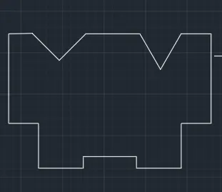
Step-2
- Draw the vertical refernce line from top mid point to bottom mid point by using Line command L enter
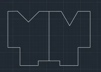
Step-3
- Draw a rectangle by using REC enter
- With dimension of (3',3') and enter
- Move the rectangle by using M Enter
- Selct the object and enter specify the mid point of the rectangle and place into the mid point of the drawing and enter
- Noe use rotate command by using RO enter
- Select the object by using cursor
- Select the mid point of the rectangle rotate towards SE 225 degrees and enter
- And erase the reference line by using E enter
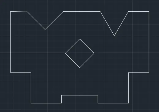
Result
Decimals
Architectural
Engineerings
Drawing-4
Drawing-5
Drawing-6
Drawing-7
Drawing-8
Drawing-9
Drawing-10
Drawing-11