Creating a Floor plan, Footing detail and Isometric view using AutoCad
AIM: Draw the drawings in Autocad
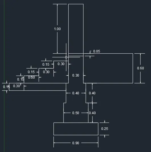
C.S of LOAD BEARING WALL OVER SPREAD FOOTINGS
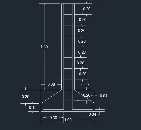
C. S. ISOLATED FOOTINGS
C.S of LOAD BEARING WALL OVER SPREAD FOOTINGS
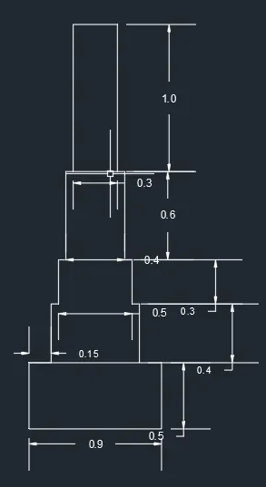
C.S of LOAD BEARING WALL SHOWING FOUNDATION DETAILS
C.S of FLOAD BEARING WALLS SHOWING FOUNDATION DEATILS
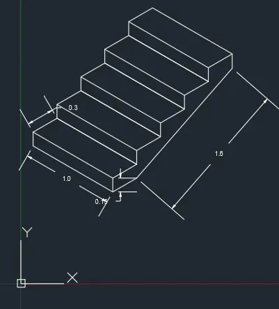
ISOMETRIC VIEW OF STEPS
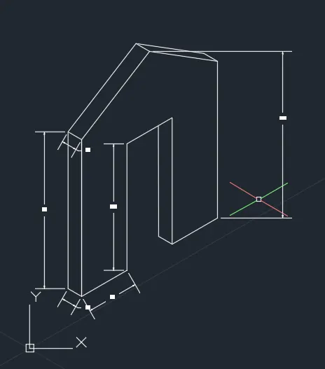
ISOMETRIC VIEW OF GABLE WALL
INTRODUCTION:
- Drawing the cross section of load bearing walls over the spread footing in autocad
- Using commands like Line, Rectangle, Offset, Trim, Copy, DS, Isoplane right , Iso plane top
PROCEDURE:
C.S of LOAD BEARING WALL OVER SPREAD FOOTINGS
- Open the Autocad new file
- Use the command Rectangle by usind REC enter
- Specify the first point (1,1)
- Specify the next point (0.90, 0.25)
- Use the command Line by using L Enter
- Specify the first point (1,1.25)
- Specify the next point (@0,0.45) and enter for closing the command
- Use the command offset by using O Enter
- Specify the offset diatance towards x direction is 0.20
- Specify the next offset distance towards the x direction is 0.60 and the click enter to close the command
- Use the line command by using L enter
- Specify the first point (1.20,1.65)
- Specify the next point (@0.05,0)
- Specify the next point (@0,0.4) and close the command by using enter or escape
- Use the line command by using L Enter
- Specify the first point (1.7,1.65)
- Specify the next point (@-0.05,0)
- Specify the next point (@0,0.4)
- Specify the next point (@-0.05,0)
- Specify the next point (@0,1.6)
- Specify the next point (@-0.30,0)
- Specify the next point (@0,-1)
- Specify the next point (@0,-0.15)
- Specify the next point (@-0.3,0)
- Specify the next point (@0,-0.15)
- Specify the next point (@-0.3,0)
- Specify the next point (@0,0.15)
- Specify the next point (@-0.3,0)
- Specify the next point (@0,-0.15)
- Specify the next point (@-0.3,0)
- Specify the next point (@0,0.15)
- Specify the next point (@1.15,0) Close the command by using escape
- Use the line command by using L Enter
- Specify the first point (0.4,2.05)
- Specify the next point (@0.9,0)
- Specify the next point (@0,0.45) Close the command by using escape
- Use the line command by using L Enter
- Specify the first point (1.6,2.65)
- Specify the next point (@1.0,0)
- Specify the next point (@0,-0.6)
- Specify the next point (@-0.95,0) Close the command by using escape
- Use the line command by using L Enter
- Specify the first point (1.3,2.6)
- Specify the next point (@3.0,0) Close the command by using escape
- Keep the dimensions bys usinG command Dim or menu bar dimensions linear
C. S. ISOLATED FOOTINGS
- Open the Autocad new file
- Use the command Line by L Enter
- Specify the first point (1,1)
- Specify the next point (@1,0)
- Specify the next point (@0,0.15)
- Specify the next point (@-1.62,1.4)
- Specify the next point (@0,1.6)
- Specify the next point (@-0.24,0)
- Specify the next point (@0,-1.6)
- Specify the next point (@-1,-1.15)
- Specify the next point (@1,0)
- Close enter in the command to close from first point
- Use the command offset by using O Enter
- Specify the offset distance of line (1,1 to @0,1.15)
- Specify the offset distance 0.04
- Specify the second offset distance is 0.92 from the first line and close the command by usind escape
- Use the command offset by using O Enter
- Specify the offset distance of line (1,1 to @1,0)
- Specify the offset distance 0.04 and close the cammnd by using close enter
- Use the command Line by L Enter
- Specify the first point (1.42,1.04)
- Specify the next point (@0,1.96)
- Specify the next point (@0.16,0)
- Specify the next point (@0,-1.96) and close the command by using escape
- Select the line of (1.42,3 to @0.16,0) and use the command copy C Enter
- Select the array option in the command box
- After selecting the array the command ask the number of items so we need to enter the 10 items with the distance of 0.20
- After copying the multiple items close the command by using escape
- Use the command trim T double to trim the lines to trim the unnessary lines
- Keep the dimensions bys usinG command Dim or menu bar dimensions linear
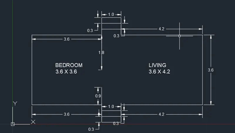
C.S of LOAD BEARING WALL OVER SPREAD FOOTINGS
- Erase the existing file by uisng erase E Enter and fully selected object
- Use the line command L Enter
- Specify the first point (1,1)
- Specify the next point (@3.6,0)
- Specify the next point (@0,-0.3)
- Specify the next point (@0,-0.3)
- Specify the next point (@0,-0.3)
- Specify the next point (@1,0)
- Specify the next point (@0,0.3)
- Specify the next point (@0,0.3)
- Specify the next point (@0,0.3)
- Specify the next point (@4.2,0)
- Specify the next point (@0,3.6)
- Specify the next point (@-4.2,0)
- Specify the next point (@0,0.3)
- Specify the next point (@0,0.3)
- Specify the next point (@0,0.3)
- Specify the next point (@-1,0)
- Specify the next point (@0,-0.3)
- Specify the next point (@0,-0.3)
- Specify the next point (@0,-0.3)
- Specify the next point (@-3.6,0)
- And close the command in command box to connect the first point
- Use the command offset O Enter
- Specify the offset distaance with the line (4.6,0.1) to (5.6,0.1)
- In through specify the offset distance 0.3 towards y direction Enter
- And select the same line and in using offset command and 0.6 towards y direction Enter
- Close the command by using escape
- Use the offset command by using O Enter
- Specify the offset distaance with the line (4.6,5.5) to (5.6,5.5)
- In through specify the offset distance 0.3 towards -y direction Enter
- And select the same line and in using offset command and 0.6 towards -y direction Enter
- Close the command by using escape
- Use the line command L Enter
- Specify the first point (4.6,4.6)
- Specify the next point (@0,-1.8)
- Close the command by using escape
- Use the line command L Enter
- Specify the first point (4.6,1)
- Specify the next point (@0,0.9)
- Close the command by using escape
- Keep the dimensions bys usinG command Dim or menu bar dimensions linear
C.S of LOAD BEARING WALL SHOWING FOUNDATION DETAILS
- Erase the existing file by uisng erase E Enter and fully selected object
- Use the Rectangle Command REC Enter
- Specify the first point (1,1)
- Specify the next point (0.9,0.45)
- Use the command Line by using L Enter
- Specify the first point (1.15,1.45)
- Specify the next point (@0,0.40)
- Specify the next point (@0.05,0)
- Specify the next point (@0,0.30)
- Specify the next point (@0.05,0)
- Specify the next point (@0,0.60)
- Specify the next point (@0,0.40)
- Specify the next point (@0.05,0)
- Specify the next point (@0,1)
- Specify the next point (@0.3,0)
- Specify the next point (@0,-1)
- Specify the next point (@0.05,0)
- Specify the next point (@0,-0.6)
- Specify the next point (@0.05,0)
- Specify the next point (@0,-0.3)
- Specify the next point (@0.05,0)
- Specify the next point (@0,-04)
- Close the command by using escape
- Use the offset command by using O Enter
- Specify the offset distance with the line (1.3,3.75) to (1.6,3.75)
- Specify the offset distance 1.0 Enter
- Select the line (1.3,3.75) to (1.6,3.75) and enter towards - y direction
- Close the command by using close enter
C.S of FLOAD BEARING WALLS SHOWING FOUNDATION DEATILS
- Erase the existing file by uisng erase E Enter and fully selected object
- Use the Rectangle Command REC Enter
- Specify the first point (1,1)
- Specify the next point (0.9,0.45)
- Use the command Line by using L Enter
- Specify the first point (1.15,1.45)
- Specify the next point (@0,0.40)
- Specify the next point (@0.05,0)
- Specify the next point (@0,0.30)
- Specify the next point (@0.05,0)
- Specify the next point (@0,0.60)
- Specify the next point (@0,0.40)
- Specify the next point (@0.05,0)
- Specify the next point (@0,1)
- Specify the next point (@0.3,0)
- Specify the next point (@0,-1)
- Specify the next point (@0.05,0)
- Specify the next point (@0,-0.6)
- Specify the next point (@0.05,0)
- Specify the next point (@0,-0.3)
- Specify the next point (@0.05,0)
- Specify the next point (@0,-04)
- Close the command by using escape
- Use the offset command by using O Enter
- Specify the offset distance with the line (1.3,3.75) to (1.6,3.75)
- Specify the offset distance 1.0 Enter
- Select the line (1.3,3.75) to (1.6,3.75) and enter towards - y direction
- Close the command by using close enter
- Keep the dimensions by using command Dim or menu bar dimensions linear
ISOMETRIC VIEW OF GABLE WALL
- It is a isometric drawing so i was doing in a 2b Moduling
- Use the line command by using L Enter
- Specify the first point (1,1)
- Specify the next point (<90,0.15)
- Specify the next point (<30,0.3)
- Specify the next point (<150,1)
- Specify the next point (<210,0.3)
- Specify the next point (<270,0.15)
- Close the command in the command box to close from first point
- Use the line command by using L Enter
- Specify the First point (1.0,1.15)
- Specify the next point (<30,1)
- Close the command by using escape
- Select the drawing by using fully selected
- And use the command Copy C Enter
- Select the base point (1,1)
- And click on array and autocad ask enter the items to array
- and click 5 enter and specify the second point is (1.2598,1.3) and exit
- Use the line command by using L Enter
- Specify the first point (1,1)
- Specify the second point (<30,0.3) and exit
- Use the line command by using L Enter
- Specify the first point (2.2990,2.5)
- Specify the second point (<270,0.15) and exit
- Use the line command by using L Enter
- Specify the first point (1.2598,1.15)
- Specify the second point (<49,1.6) and exit
- Keep the dimensions by using command Dim or menu bar dimensions linear
ISOMETRIC VIEW OF GABLE WALL
- It is a isometric drawing
- use the isoplane option in status bar
- Use the line command by using L Enter and use the isoplane right
- Specify the first point (1,1)
- Specify the next point towards NE direction 1.0 Enter
- Specify the next point towards N direction 2.42 Enter
- Specify the next point towards NE direction 1.0 Enter
- Specify the next point towards S direction 2.42 Enter
- Specify the next point towards NE direction 1.0 Enter
- Specify the next point towards N direction 3 Enter and exit
- Use the line command L Enter and use isoplane top in status bar
- Specify the first point (1,1)
- Specify the next point towards NW direction 0.3 Enter
- And change the isoplane top to isoplane right Specify the point towards N Direction 3.0 enter
- And change the isoplane right to isoplane top Specify the point towards SE Direction 0.3 enter and exit
- Use the line command by using L Enter
- Specify the first point (2.7321,2.0)
- And change the isoplane right to isoplane top Specify the point towards NW Direction 0.3 enter
- And change the isoplane top to isoplane right Specify the point towards N Direction 3.0 enter and Exit
- Use the line command by using L Enter
- Specify the first point (1,1)
- use the isoplane right towards the NE direction and 1.5 Enter
- Specify the next point (@0,3.25) and exit
- Use the command Strech enter to the refernce line 3.25 and after Erase the line by using erase Enter
- Keep the dimensions by using command Dim or menu bar dimensions linear
RESULT:
Note : I didnt copy any projects i just copy my test for speed up my challange Thank you