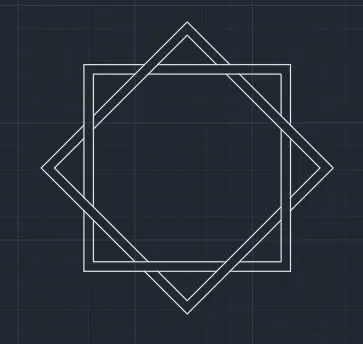
Drafting of various geometries using Chamfer, Fillet tool in AutoCad
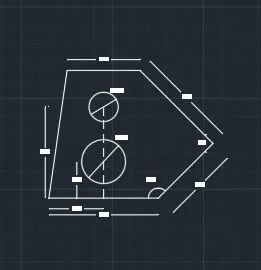
1) AIM :- complete the given drawings using autocad software in decimal system
PROCEDURE :-
- Open autocad drawing page.
- Select 'new'.
- Set the default template as imperial, enter 'un' and select decimal system and unit as inches.
- select circle option and draw a circle with diameter 1.2 units. draw a perpenindicular from the centre of the circle of length 1 unit. from the end of the perpendicular draw lines of 1.5 units each to either side .
- Then turn on o snap and draw line of given measurement at angle 135 degree. continue drawing lines as per the given drawing and angles.
- Draw another circle of diametr 0.8 at a distance of 2.5 units from the base line and in line with the first circle
- mark dimensions using dimension option, dimangular,dimcircle
- The resulted drawing as per the question is obtained as per the drawing below in either way
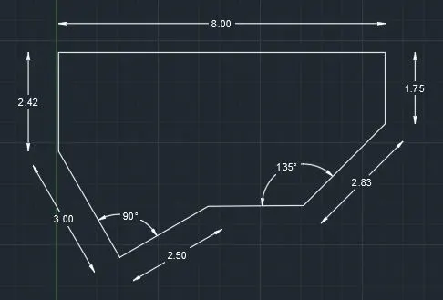
2) AIM :- complete the given drawings using autocad software in architectural system
PROCEDURE :-
- Open autocad drawing page.
- Select 'new'.
- Set the default template as imperial, enter 'un' and select archiectural system and unit as feet.
- change all the units to feet before starting to draw.
- start drawing by turning orthomode on and using dimensions in the given figure.
- use osnap to draw lines at an angle and use rotate option wherever required.
- mark dimensions using dimension option, dimangular
- The resulted drawing as per the question is obtained as per the drawing below in either way
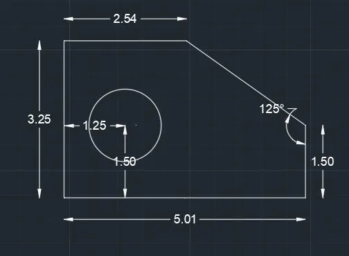
3) AIM :- complete the given drawings using autocad software in engineering system
PROCEDURE :-
- Open autocad drawing page.
- Select 'new'.
- Set the default template as imperial, enter 'un' and select engineering system and unit as feet.
- change all the units to feet before starting to draw.
- start drawing by turning orthomode on and using dimensions in the given figure.
- use osnap to draw lines at an angle and use rotate option wherever required.
- use circle option to draw a circle of diameter 1.5 feet.
- mark dimensions using dimension option, dimangular
- The resulted drawing as per the question is obtained as per the drawing below in either way
4) AIM :- complete the given drawings using autocad software in decimal system
PROCEDURE :-
- Open autocad drawing page.
- Select 'new'.
- Set the default template as imperial, enter 'un' and select engineering system and unit as inches.
- start drawing by turning orthomode on and using dimensions in the given figure.
- mark dimensions using dimension option, dimangular
- The resulted drawing as per the question is obtained as per the drawing below in either way
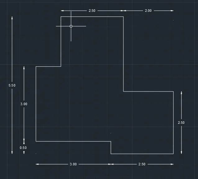
5) AIM :- complete the given drawings using autocad software in decimal system
PROCEDURE :-
- Open autocad drawing page.
- Select 'new'.
- Set the default template as imperial, enter 'un' and select engineering system and unit as inches.
- start drawing by turning orthomode on and using dimensions in the given figure.
- use offset option and circle option to draw the circles as per given dimensions
- mark dimensions using dimension option, dimangular
- The resulted drawing as per the question is obtained as per the drawing below in either way
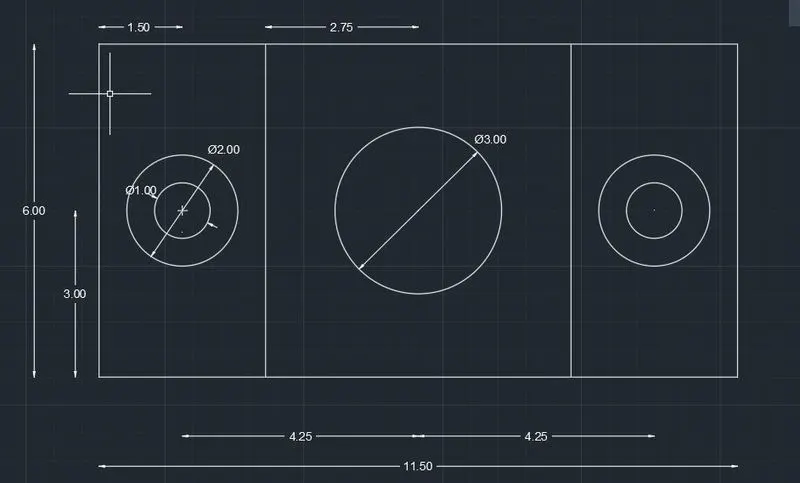
6) AIM :- complete the given drawings using autocad software in decimal system
PROCEDURE :-
- Open autocad drawing page.
- Select 'new'.
- Set the default template as imperial, enter 'un' and select engineering system and unit as inches.
- start drawing by turning orthomode on and using dimensions in the given figure.
- use offset option to draw as per given dimensions
- mark dimensions using dimension option, dimangular
- The resulted drawing as per the question is obtained as per the drawing below in either way
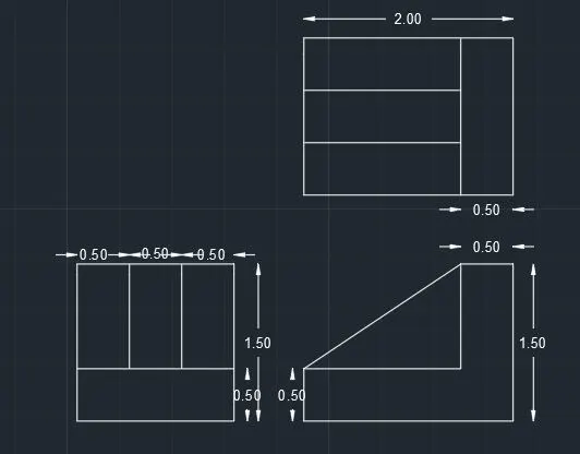
7) AIM :- complete the given drawings using autocad software in decimal system
PROCEDURE :-
- Open autocad drawing page.
- Select 'new'.
- Set the default template as imperial, enter 'un' and select engineering system and unit as inches.
- start drawing by turning orthomode on and using dimensions in the given figure.
- use offset option to draw as per given dimensions and then use fillet option to curve the edges as per drawing given
- draw circles as required
- mark dimensions using dimension option, dimangular
- The resulted drawing as per the question is obtained as per the drawing below in either way
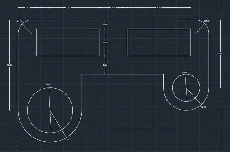
8) AIM :- complete the given drawings using autocad software in decimal system
PROCEDURE :-
- Open autocad drawing page.
- Select 'new'.
- Set the default template as imperial, enter 'un' and select engineering system and unit as inches.
- start drawing by turning orthomode on and using dimensions in the given figure.
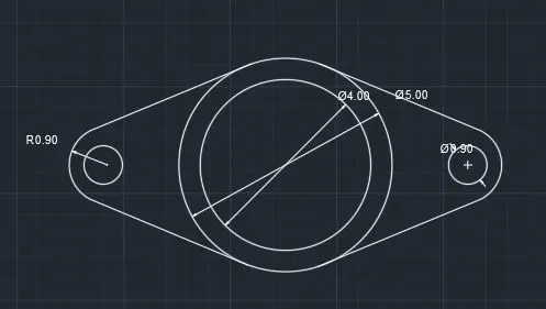
- draw the 3 two circles at end of line of length 8.55 and another 2 circles in the centre with diameters 4 and 5.
- extend the line joining the centrs of the 3 circles .
- now draw a tangent from top of the circle till the extended line.mirror this line to the bottom half of the figure
- fillet the junction of the two lines with radius of 0.9.
- mirror this image of the 2 lines and the filleted radius to the other side
- mark dimensions using dimension option, dimangular
- The resulted drawing as per the question is obtained as per the drawing below in either way
10) AIM :- complete the given drawings using autocad software in decimal system
PROCEDURE :-
- Open autocad drawing page.
- Select 'new'.
- Set the default template as imperial, enter 'un' and select engineering system and unit as inches.
- start drawing by turning orthomode on and using dimensions in the given figure.
- draw a square of dimension 4 x4 using the rectangle option
- copy that and rotate it to 45 degrees .move an dplace this rotate dsquare at the mid point of the base of the first square
- use offset option on both the squares .
- now trim the squares to make figure as given in the question
- mark dimensions using dimension option, dimangular
- The resulted drawing as per the question is obtained as per the drawing below in either way