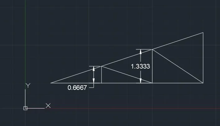
Creation of geometries by Coordinate system methods using AutoCad
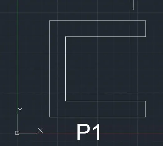
P1) AIM :- For drawing P1 , absolute coordinate and relative coordinate system is used to to complete the drawings using autocad software.
PROCEDURE :-
- Open autocad drawing page.
- Select 'new'.
- Set the default template as imperial, enter 'un' and select decimal system and unit as inches.
- Select line tool from tool bar, switch on orthomode and begin drawing.Enter the points below and after entering each pair of coordinates press enter.
- If absolute method is followed, the points are:-(2,1),(8,1),(8,2),3,2),(3,6),(8,6),(8,7),(2,7),(2,1)
- If relative method was followed , the points would be:- (2,1),(@6,0),(@0,1),(@-5,0),(@0,4),(@5,0),(@0,1),(@-6,0) and close
- The resulted drawing as per the question is obtained as per the drawing below in either way
- The @ symbol shifts the coordinate system w.r. t the previous point used
-
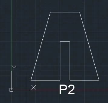
P2) AIM :- For drawing P2 , absolute coordinate and relative coordinate system is used to to complete the drawings using autocad software.
PROCEDURE :-
- Open autocad drawing page.
- Select 'new'.
- Set the default template as imperial, enter 'un' and select decimal system and unit as inches.
- Select line tool from tool bar, switch on orthomode and begin drawing.Enter the points below and after entering each pair of coordinates press enter.
- If absolute method is followed, the points are:-(2,1),(5,1),(6,1),(9,1),(5,5),(6,5),(7,8),(4,8),(2,1)
- If relative method was followed , the points would be:- (2,1),(@3,0),(@0,4),(@1,0),(@0,-4),(@3,0),(@-2,7),(@-3,0) and close
- The resulted drawing as per the question is obtained as per the drawing below in either way
- The @ symbol shifts the coordinate system w.r. t the previous point used
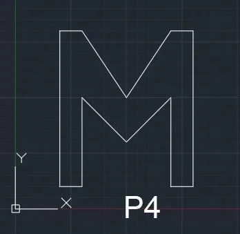
P4) AIM :- For drawing P4 , absolute coordinate system is used to to complete the drawing using autocad software.
PROCEDURE :-
- Open autocad drawing page.
- Select 'new'.
- Set the default template as imperial, enter 'un' and select decimal system and unit as inches.
- Select line tool from tool bar, switch on orthomode and begin drawing. Enter the points below and after entering each pair of coordinates press enter.
- As the absolute method is followed, the points are:-(2,1),(3,1),(3,5),(5,3),(7,5),(7,1),(8,1),(8,8),(7,8),(5,5),(3,8),(2,8),(2,1)
- The resulted drawing as per the question is obtained as per the drawing below
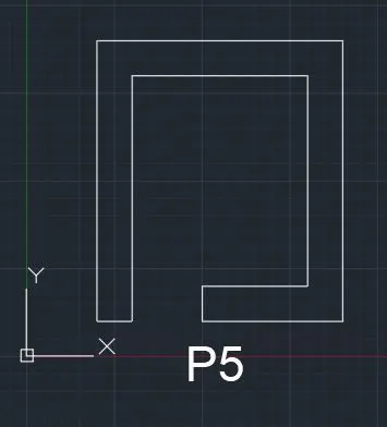
P5) AIM :- For drawing P5 , absolute coordinate system is used to to complete the drawing using autocad software.
PROCEDURE :-
- Open autocad drawing page.
- Select 'new'.
- Set the default template as imperial, enter 'un' and select decimal system and unit as inches.
- Select line tool from tool bar, switch on orthomode and begin drawing. Enter the points below and after entering each pair of coordinates press enter.
- As the absolute method is followed, the points are:-(2,1),(3,1),(3,8),(8,8),(8,2),(5,2),(5,1),(9,1),(9,9),(2,9),(2,1)
- The resulted drawing as per the question is obtained as per the drawing below
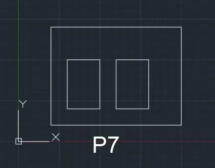
P7) AIM :- For drawing P7, absolute coordinate system is used to to complete the drawing using autocad software.
PROCEDURE :-
- Open autocad drawing page.
- Select 'new'.
- Set the default template as imperial, enter 'un' and select decimal system and unit as inches.
- Select line tool from tool bar, switch on orthomode and begin drawing. Enter the points below and after entering each pair of coordinates press enter.
- As the absolute method is followed, the points are:-(2,1),(10,1),(10,7),(2,7),(2,1),(3,2),(5,2),(5,5),(3,5),close,(6,2),(8,2),(8,5),(6,5),close
- The resulted drawing as per the question is obtained as per the drawing below
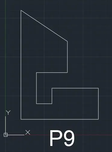
P9) AIM :- For drawing P9, absolute coordinate system is used to to complete the drawing using autocad software.
PROCEDURE :-
- Open autocad drawing page.
- Select 'new'.
- Set the default template as imperial, enter 'un' and select decimal system and unit as inches.
- Select line tool from tool bar, switch on orthomode and begin drawing. Enter the points below and after entering each pair of coordinates press enter.
- As the absolute method is followed, the points are:-(1,1),(6,1),(6,3),(3,3),(3,2),(2,2),(2,4),(4,4),(4,6),(1,8),close
- The resulted drawing as per the question is obtained as per the drawing below
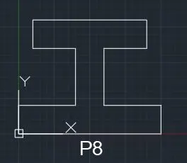
P8) AIM :- For drawing P8, absolute coordinate system is used to to complete the drawing using autocad software.
PROCEDURE :-
- Open autocad drawing page.
- Select 'new'.
- Set the default template as imperial, enter 'un' and select decimal system and unit as inches.
- Select line tool from tool bar, switch on orthomode and begin drawing. Enter the points below and after entering each pair of coordinates press enter.
- As the absolute method is followed, the points are:-(0,0),(10,0),(10,2),(6,2),(6,6),(9,6),(9,8),(1,8),(1,6),(4,6),(4,2),(0,2),close
- The resulted drawing as per the question is obtained as per the drawing below
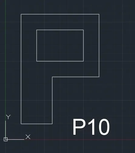
P10) AIM :- For drawing P10, absolute coordinate system is used to to complete the drawing using autocad software.
PROCEDURE :-
- Open autocad drawing page.
- Select 'new'.
- Set the default template as imperial, enter 'un' and select decimal system and unit as inches.
- Select line tool from tool bar, switch on orthomode and begin drawing. Enter the points below and after entering each pair of coordinates press enter.
- As the absolute method is followed, the points are:-(1,1),(3,1),(3,4),(6,4),(6,8),(1,8),close,(2,5),(5,5),(5,7),(2,7),close
- The resulted drawing as per the question is obtained as per the drawing below
P11) AIM :- For drawing P11, absolute coordinate system is used to to complete the drawing using autocad software.
PROCEDURE :-
- Open autocad drawing page.
- Select 'new'.
- Set the default template as imperial, enter 'un' and select decimal system and unit as inches.
- Select line tool from tool bar, switch on orthomode and begin drawing. Enter the points below and after entering each pair of coordinates press enter.
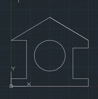
- As the absolute method is followed, the points are:-(0,0),(10,0),(10,1),(8,1),(8,5),(10,5),(10,6),(5,9),(0,6),(2,6),(2,1),(0,1)close
- Select circle option and draw the circle with its centre at (5,4) with radius 1
- The resulted drawing as per the question is obtained as per the drawing below
P12) AIM :- For drawing P12, absolute coordinate system is used to to complete the drawing using autocad software.
PROCEDURE :-
- Open autocad drawing page.
- Select 'new'.
- Set the default template as imperial, enter 'un' and select decimal system and unit as inches.
- Select line tool from tool bar, switch on orthomode and begin drawing. Enter the points below and after entering each pair of coordinates press enter.
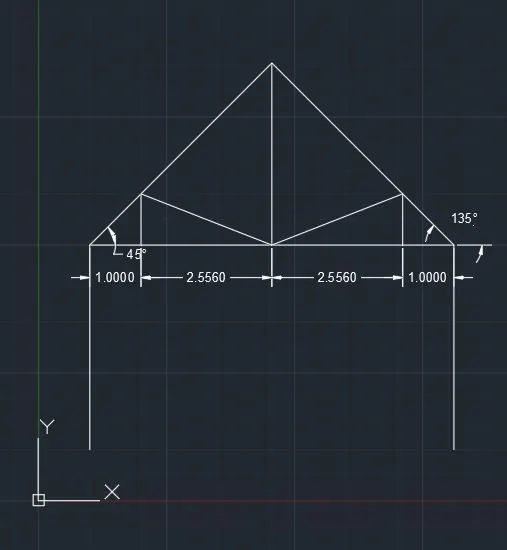
- As the absolute method is followed, the points are:-(1,1),(1,5),(2,5),(4.556,5),(7.112,5),(8.112,5),(8.112,1)
- Select line, turn on o snap and draw line at inclination of 45 degree from points (1,5) and (8.112,5)
- draw permindiculars from the points ( 2,5), (4.556,5),(7.112,5)
- trim the unwanted lines
- The resulted drawing as per the question is obtained as per the drawing below
P13) AIM :- For drawing P13, absolute coordinate system is used to to complete the drawing using autocad software.
PROCEDURE :-
- Open autocad drawing page.
- Select 'new'.
- Set the default template as imperial, enter 'un' and select decimal system and unit as inches.
- Select line tool from tool bar, switch on orthomode and begin drawing. Enter the points below and after entering each pair of coordinates press enter.
- As the absolute method is followed, the points are:-(1,1),(3,1),(5,1),(7,1),(7,3),(1,1)
- draw permindiculars from the points ( 3,1),(5,1). Join points (3,1.667), (5,1) and (5,2.33),(7,1)
- trim the unwanted lines
- The resulted drawing as per the question is obtained as per the drawing below