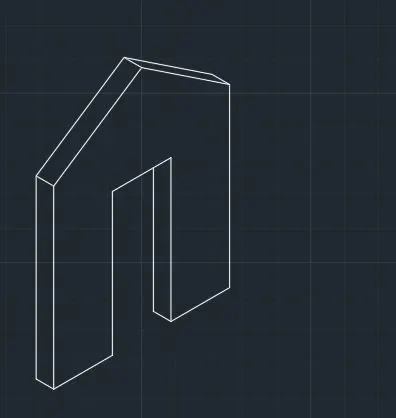
Creating a Floor plan, Footing detail and Isometric view using AutoCad
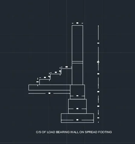
C1 ) Aim:- To draw cross section of load bearing wall on spread footing using autocad software
procedure :
- Open 'new' cad drawing. Enter 'UNITS' and select unit as inch and decimal system.switch on the orthomode.
- select dimension after selectiong rectangle option and draw 3 recatangles of dimensions (0.9,0.25),(0.5,0.4) and (0.4,0.4).
- place the three reactnagles on top of one another , the biggest at the bottom and the smallest at the top, such that their mid points are alligned on top of each other.
- next start drawing the steps. select line option and keep drawing horizontal and vertical lines as per dimensions given in the question.
- next ,draw the load bearing wall using line option according to dimensions in the question.
- trim off any uneccesary lines using trim option and dimension the drawing with the help of dimension and dimcontinous option.
- The resulting figure will look like the figure below.
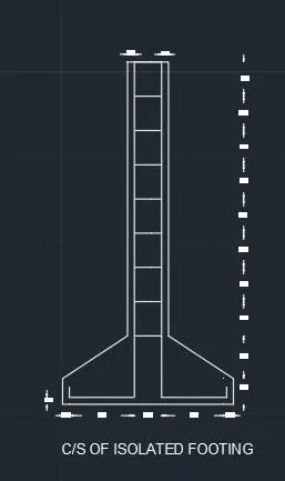
C2 ) Aim:- To draw cross section of isolated footing using autocad software
procedure :
- Open 'new' cad drawing. Enter 'UNITS' and select unit as inch and decimal system. switch on orthomode
- start drawing the isolated footing using line option. The dimensiosn are given in the question.
- after drawing the footing draw the column and clos ethe figure.
- draw the reinforcement of the footing separately as per dimensions in the figure.
- select the whole reinforcemnet drawing and move it. make sure while moving , the midpoint of the top horozontal reinforcement is selected an dplaced at the midpoint of the horizontal line at the top of the column.
- dimension the figure using dimension tool.
- The resulting figure will look like the figure below.
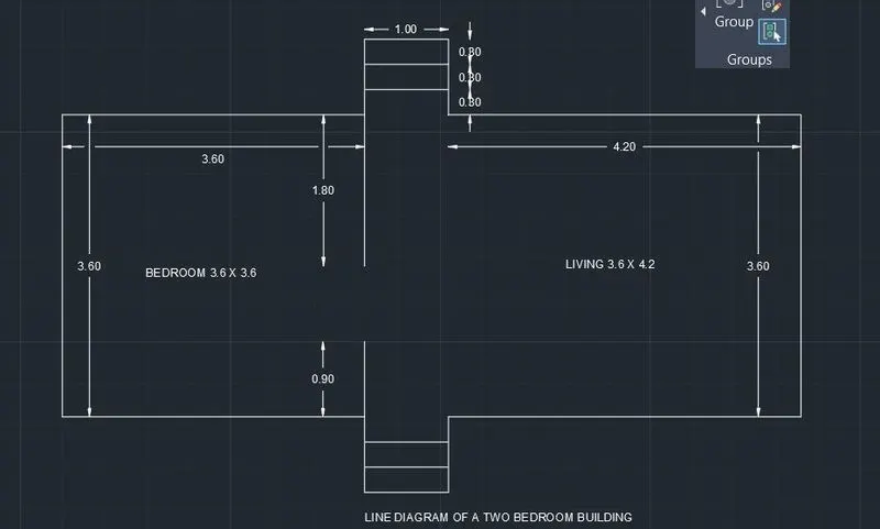
C3 ) Aim:- To draw line diagram of a two bedroom building using autocad software
procedure :
- Open 'new' cad drawing. Enter 'UNITS' and select unit as inch and decimal system.
- start drawing the line drawing using line option.switch on the orthomode. The dimensions are given in the question.
- dimension the figure using dimension tool. use the option dimbreak on dimension lines that are intersecting each other.
- The resulting figure will look like the figure below.
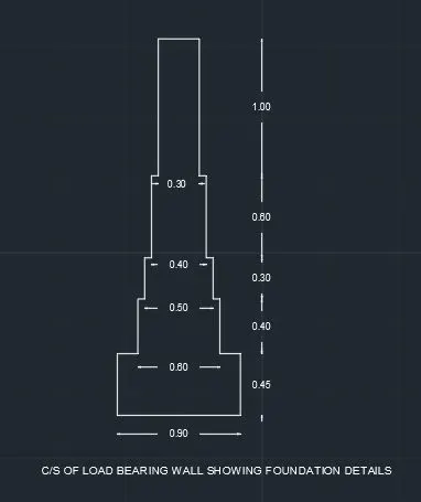
C4) Aim:- To draw cross section of load bearing wall showing foundation details, using autocad software
procedure :
- Open 'new' cad drawing. Enter 'UNITS' and select unit as inch and decimal system.switch on the orthomode.
- select dimension after selectiong rectangle option and draw 4 recatangles of dimensions (0.9x0.45),(0.6x0.4),(0.5x0.3), (0.4x0.6) and (0.3x1)
- place the three reactnagles on top of one another respectively, such that their mid points are alligned on top of each other.
- trim off any uneccesary lines using trim option and dimension the drawing with the help of dimension and dimcontinous option.
- The resulting figure will look like the figure below.
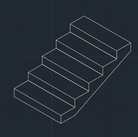
C5) Aim:- To draw isometric view of steps using autocad software
procedure :
- Open 'new' cad drawing. Enter 'UNITS' and select unit as inch and decimal system.switch on the orthomode.
- switch on isometric drafting mode and select isoplane top .
- draw rectangle of dimension 1 x 0.3 using line option.(ie. the top plane of the bottom step)
- select isoplane left and draw anothe rrectangle of dimension1 x 0.15 (ie. the side plane of the first step )
- select and copy the step and paste it on top of one anotherto get a total number of 5 steps
- draw the waist slab of the steps.
- The resulting figure will look like the figure below.
C6) Aim:- To draw isometric view of gable wall using autocad software
procedure :
- Open 'new' cad drawing. Enter 'UNITS' and select unit as inch and decimal system.switch on the orthomode.
- switch on isometric drafting mode and select isoplane left.
- draw rectangle of dimension 0.3 x 3 using line option.(ie. the side plane of the gable wall)
- select isoplane right and draw the front plane of gable wall and the door
- draw a straight line of 4 units from mid point of the bottom of the door frame. this is the top of the roof. draw the rest of the sloping roof in isoplane left and isoplane right.(the roof height is given as 3.25 units as per question but the roof height then ,will be very small )
- The resulting figure will look like the figure below.