Drafting of various geometries using Chamfer, Fillet tool in AutoCad
AIM : Drafting of various geometries using Chamfer, Fillet tool in AutoCad.
Answer : First i will explain what is Chamfer and Fillet in AutoCad
Fillet: is a tool in AutoCad which is used for rounding corners of any object as per requirement in drawing.
It is required when object dosent have sharp edges in that case we can use Fillet tool for roundning the corners.
Chamfer : Chamfer is another tool in AutoCad which is used to provide sloped or angled edges of any object.
Now i will draw each drawings as mentioned in attachment by using Chamfer and Fillet tool.
1.) Here is the first drawing.
Commands used for drawing : Line tool, Circle, Annotations
Procedure:
a.) Click on AutoCad icon on the top left side of screen, go to the new and then drawings
b.) Select Matric from start from scratch option
c.) Go to the advance set-up
d.) Select Decimal as a unit
e.) Put 0.00 for precision
f.) Click next, and select Decimal Degrees
g.) Click next, Select Angle measure from North (0 will be for North) and click next
h.) Select angle direction, Clockwise and click next
i.) Select area Width as 420 and Length as 250 and Click Finish.
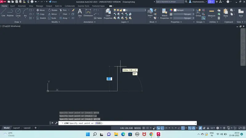
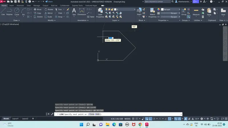
j.) Select Line tool and specify first point as 0,0
k.) Specify next point as @3<90
l.) Specify next point as @2.12<45
m.) Specify next point as @2.83<315
n.) Specify next point as @2<180
o.) Now join to the first point and close the loop
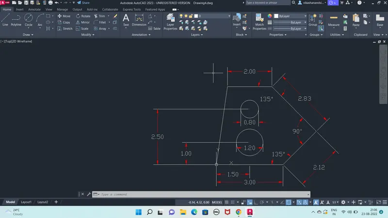
p.) Now select Circle tool and put 1.5,1 and diameter as 1.20
q.) Now again select Circle tool and put 1.5,2.50 and diameter as 0.80
r.) Select Annotation tool and show each dimension and angels.
Result :
2.) Now coming to the second drawing.
Procedure :
a.) Click on AutoCad icon on the top left side of screen, go to the new and then drawings
b.) Select Imperial from start from scratch option
c.) Go to the advance set-up
d.) Select Architectural as a unit
e.) Put 0'-0'' for precision
f.) Click next, and select Decimal Degrees
g.) Click next, Select Angle measure from East (0 will be for East) and click next
h.) Select angle direction, Counter Clockwise and click next
i.) Select Limits as 0'-0'', 0'-0'' and 12'-0'', 9',0''
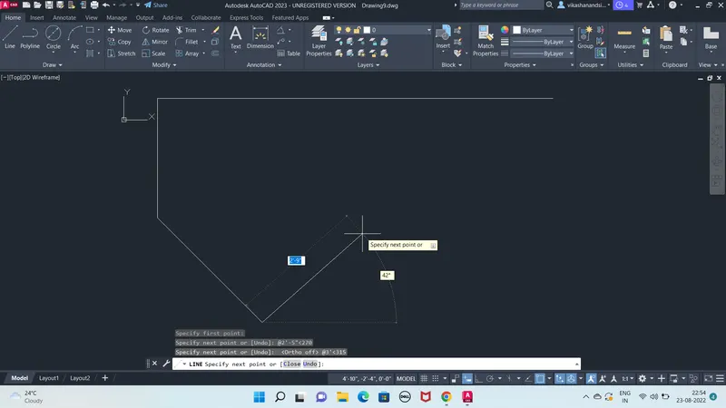
j.) Specify first point as @8'-0"<0
k.) Specify second point as @2'-5"<270
l.) Specify third point as @3'-0"<315
m.) Specify forth point as @2'-6''<29
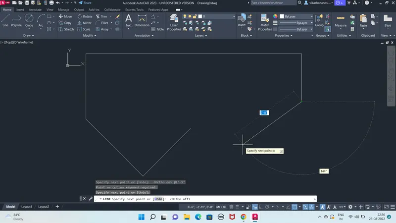
n.) Select another end of 8' and specify next point as @1'-9"<270
m.) Specify next point as @2'-10"<225.5
n.) And Close the loop by joining last point
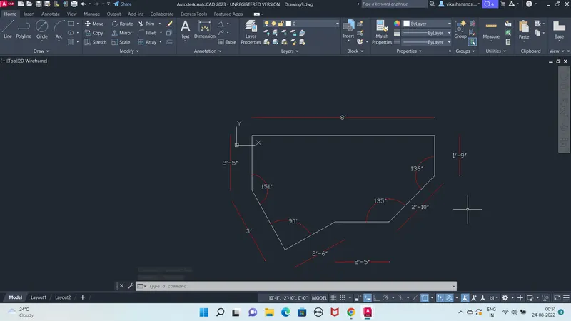
3.) Now coming to third drawing
Procedure :
a.) Click on AutoCad icon on the top left side of screen, go to the new and then drawings
b.) Select Imperial from start from scratch option
c.) Go to the advance set-up
d.) Select Engineering as a unit
e.) Put 0'-0'' for precision
f.) Click next, and select Decimal Degrees
g.) Click next, Select Angle measure from East (0 will be for East) and click next
h.) Select angle direction, Counter Clockwise and click next
i.) Select Limits as 0'-0'', 0'-0'' and 12'-0'', 9',0''
j.) Specify first point as @2'-6.5"<180
k.) Specify second point as @3'-3"<270
l.) Specify third point as @5'-0.1"<0
m.) Specify fourth point as @1'-6.0"<90
n.) Disable ortho mode and join to first point to complete loop
m.) for circle specify center point as 1'-3", 1'-6"
o.) Select circle tool and put diameter 1'-6.0"
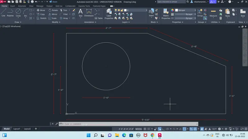
4.) Now coming to the 4th Drawing.
Procedure:
a.) Click on AutoCad icon on the top left side of screen, go to the new and then drawings
b.) Select Matric from start from scratch option
c.) Go to the advance set-up
d.) Select Decimal as a unit
e.) Put 0.00 for precision
f.) Click next, and select Decimal Degrees
g.) Click next, Select Angle measure from East
h.) Select angle direction, Counter Clockwise and click next
i.) Select area Width as 420 and Length as 250 and Click Finish.
j.) Select Line tool and specify first point as 0,0
k.) Specify 1st point as @2.5<0
l.) Next point as @3<270
m.) Next point as @2<0
n.) Next point as @2.5<270
o.) Next point as @2.5<180
p.) Next point as @0.5<90
q.) Next point as @3<180
r.) Next point as @3.50<90
t.) Next point as @1.00<0
u.) Join to the first point to close the loop.
Result:
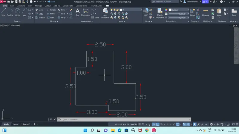
5.) Now coming to the 5th Drawing.
Command used : Line, Circle, Copy, Offset, Annotations
Procedure:
a.) Click on AutoCad icon on the top left side of screen, go to the new and then drawings
b.) Select Matric from start from scratch option
c.) Go to the advance set-up
d.) Select Decimal as a unit
e.) Put 0.00 for precision
f.) Click next, and select Decimal Degrees
g.) Click next, Select Angle measure from East
h.) Select angle direction, Counter Clockwise and click next
i.) Select area Width as 420 and Length as 250 and Click Finish.
j.) Select Line tool and specify first point as 0,0
k.) Specify 1st point as @11.5<0
l.) Next point @6.00<270
m.) Next point @11.5<180
n.) Join to the first point to close the loop.
o.) Select line tool and click 3m from first line and join perpendicularly to bottom line
p.) Type copy and select perpendicular line and put distance of 5.50
q.) Select circle tool , specify center point as 1.5, 3.0 and enter diameter as 1m
r.) Type offset in command bar, click top point of circle and put offset value as 0.5.
s.) Select both circle and type copy in command bar and put at distance of 8.5m
t.) Select circle tool , specify center point as 5.75, 3.0 and enter diameter as 3m
Result :
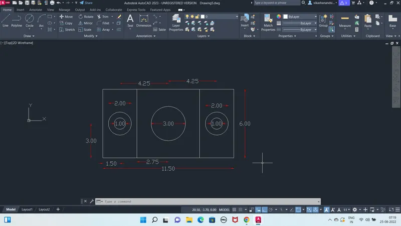
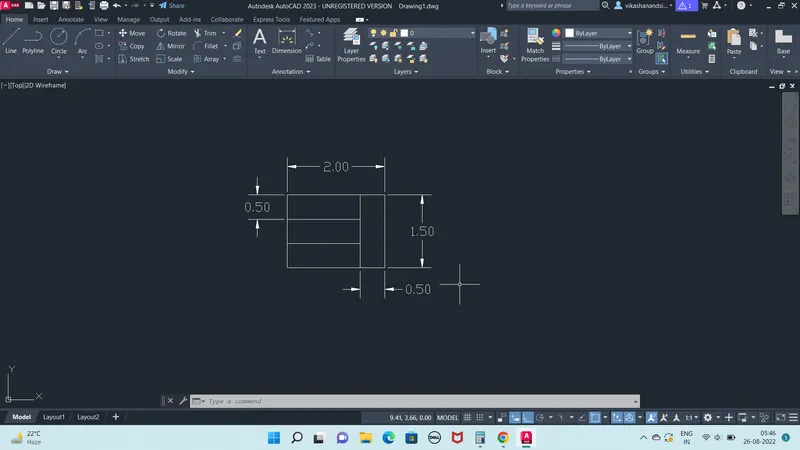
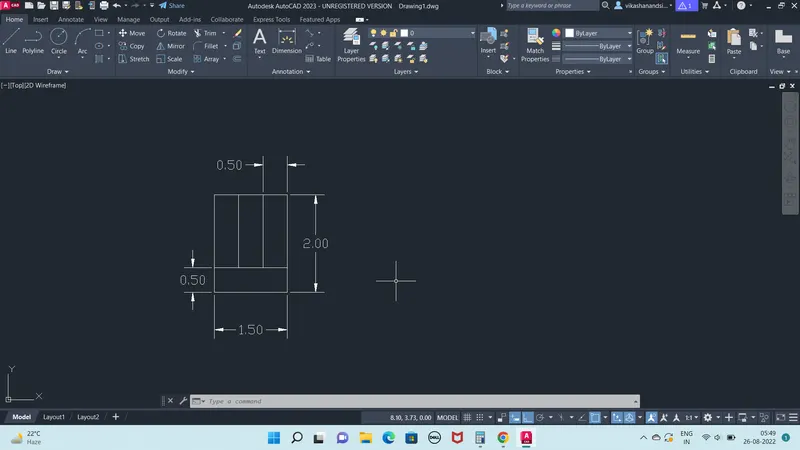
6.) Now coming to the 6th Drawing.
Command used : Line, Circle, Copy, Offset, Annotations
Procedure:
a.) Click on AutoCad icon on the top left side of screen, go to the new and then drawings
b.) Select Matric from start from scratch option
c.) Go to the advance set-up
d.) Select Decimal as a unit
e.) Put 0.00 for precision
f.) Click next, and select Decimal Degrees
g.) Click next, Select Angle measure from East
h.) Select angle direction, Counter Clockwise and click next
i.) Select area Width as 420 and Length as 250 and Click Finish.
j.) Select Line tool and specify first point as 0,0
k.) Select line tool and give a length of 2m
l.) select offset tool and apply it on every 0.5m intervals
m.) Select offset tool and apply it from LHS at 0.5m distance
n.) Trim unwanted lines.
o.) Select rotate tool and rotate the whole plot by selecting all lines
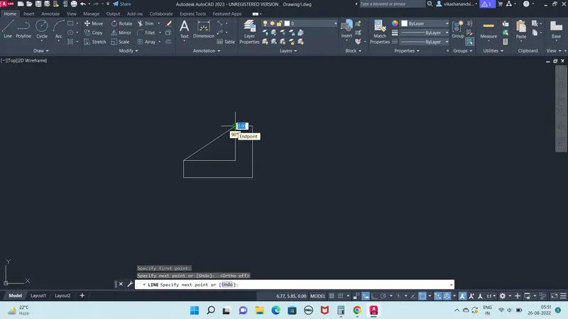
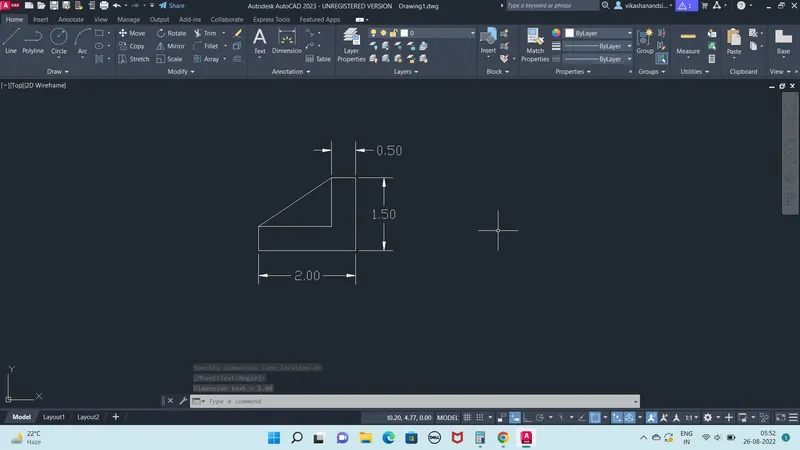
p.) Select line tool and specify next point as @1.5<270
q.) Specify next point as @1.5<180, next point as @0.5<90 and so on
r.) Select line tool, disable ortho mode and join both points.
Result:
7.) Now coming to the 7th drawing
Command used : Line, Fillet, Arc, Trim
Procedure:
a.) Click on AutoCad icon on the top left side of screen, go to the new and then drawings
b.) Select Matric from start from scratch option
c.) Go to the advance set-up
d.) Select Decimal as a unit
e.) Put 0.00 for precision
f.) Click next, and select Decimal Degrees
g.) Click next, Select Angle measure from East
h.) Select angle direction, Counter Clockwise and click next
i.) Select area Width as 420 and Length as 250 and Click Finish.
j.) Select Line tool and specify first point as 0,0
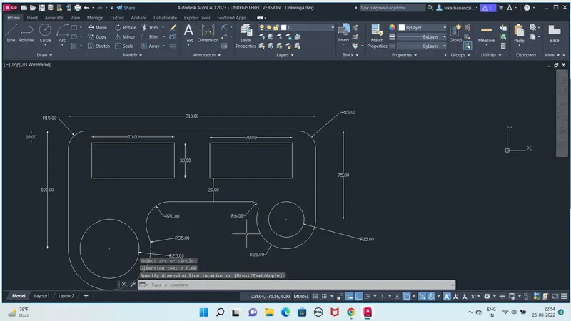
k.) Select Line tool and draw a line of 210 , 100 & 75 respectively
l.) Select a rectangular tool and specify length 70 & Width 30 from 20m distance from LHS
m.) Select rectangular shape, copy it and paste it at a distance of 30m
n.) Select circle tool and put diameter of 50 and 30 respectively.
o.) Select arc (start end centre) of radius 35 and 25 respectively
p.) Select fillet tool and specify radius as 20 & 6 for LHS & RHS
q.) Select fillet tool of radius 15 and select horizontal & Verticles lines. Trim unwanted lines.
Result :
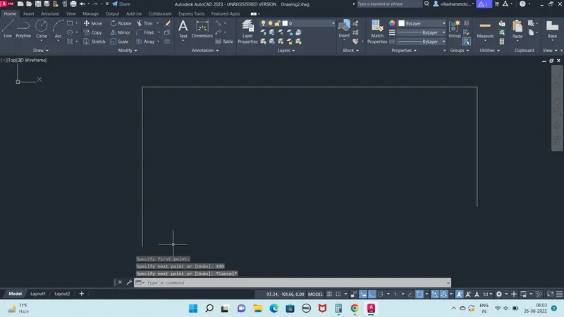
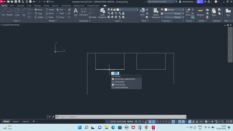
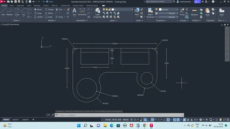
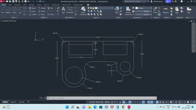
8.) Now coming to the 8th drawing
Command used : Circle, Fillet, Arc, Trim, Offset
Procedure:
a.) Click on AutoCad icon on the top left side of screen, go to the new and then drawings
b.) Select Matric from start from scratch option
c.) Go to the advance set-up
d.) Select Decimal as a unit
e.) Put 0.00 for precision
f.) Click next, and select Decimal Degrees
g.) Click next, Select Angle measure from East
h.) Select angle direction, Counter Clockwise and click next
i.) Select area Width as 420 and Length as 250 and Click Finish.
j.) Select Line tool and specify first point as 0,0
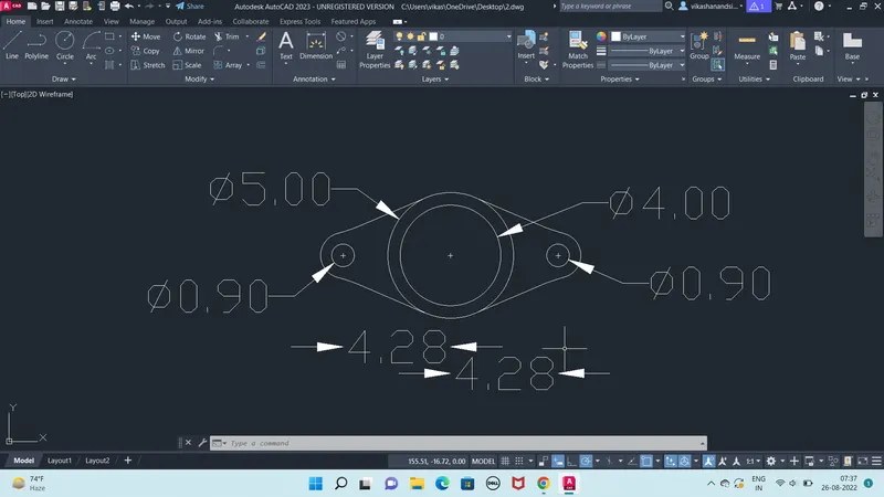
k.) Select a line tool and draw a line of 8.55
l.) Draw circles of diameter 0.9 at both sides of line respectively
m.) Select a circle tool of diameter 4 , select offset tool and draw another circle of diameter 5
n.) Select arc of radius 0.90 for both sides of circles
m.) Select line and close all loops and trim unwanted lines.
9.) Now coming to the 10th Drawing
Command Used : Line, Copy, Move, Trim
Procedure:
a.) Click on AutoCad icon on the top left side of screen, go to the new and then drawings
b.) Select Matric from start from scratch option
c.) Go to the advance set-up
d.) Select Decimal as a unit
e.) Put 0.00 for precision
f.) Click next, and select Decimal Degrees
g.) Click next, Select Angle measure from East
h.) Select angle direction, Counter Clockwise and click next
i.) Select area Width as 420 and Length as 250 and Click Finish.
j.) Select Line tool and specify first point as 0,0
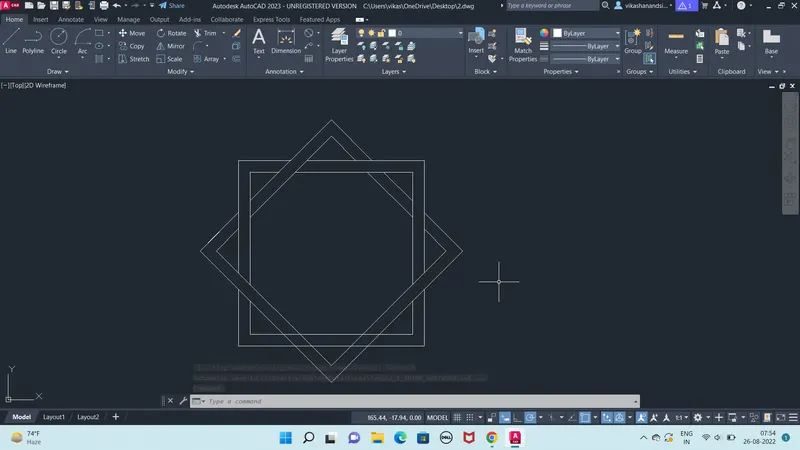
k.) Select a line tool and draw a square of any length
l.) select offset and create a another square of 0.5 offset both sides
m.) Copy it and paste nearby and use rotate command and put over diagonally on existing plot
n.) trim unwanted lines.
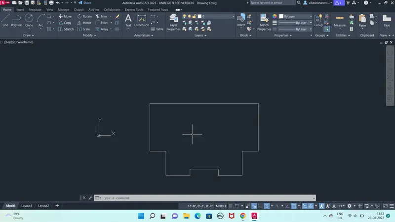
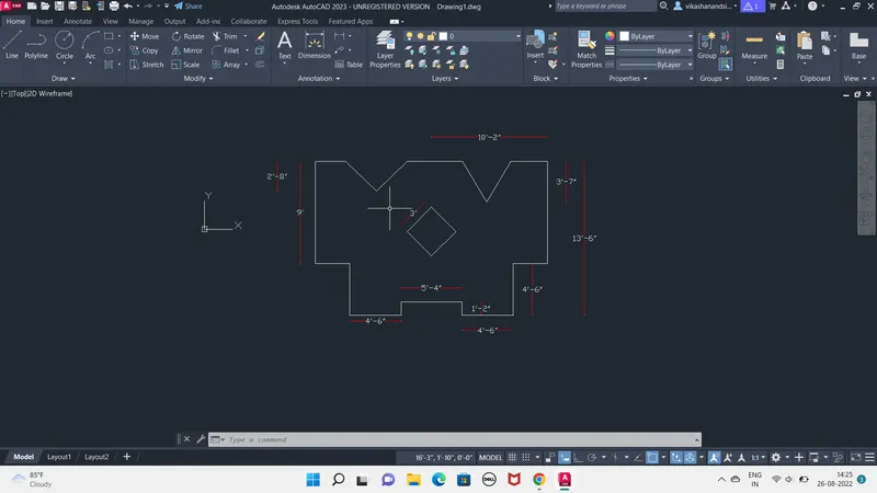
10.) This is the 11th Drawing which i'm going to plot here
Command Used : Line, Rectangle, Rotate, Mirror, Move, Trim
Procedure :
a.) Click on AutoCad icon on the top left side of screen, go to the new and then drawings
b.) Select Imperial from start from scratch option
c.) Go to the advance set-up
d.) Select Engineering as a unit
e.) Put 0'-0'' for precision
f.) Click next, and select Decimal Degrees
g.) Click next, Select Angle measure from East (0 will be for East) and click next
h.) Select angle direction, Counter Clockwise and click next
i.) Select Limits as 0'-0'', 0'-0'' and 12'-0'', 9',0''
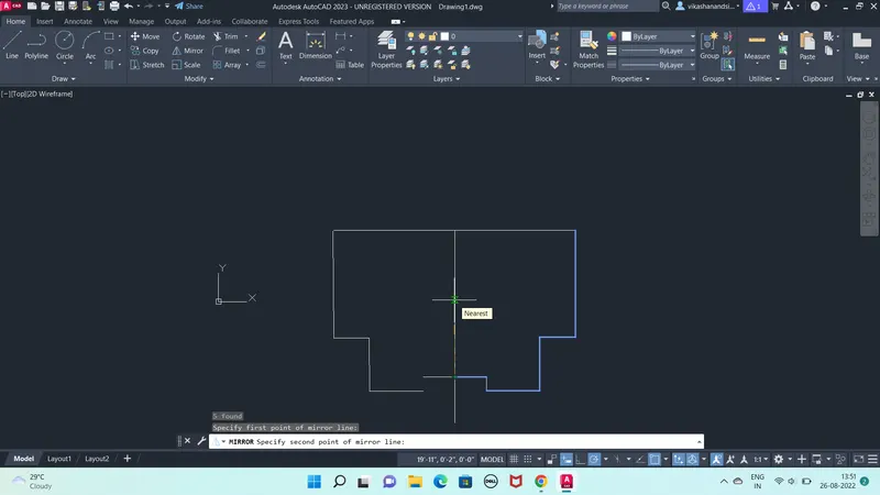
j.) Select line tool and specify first point as @9'-0"<270
k.) Next point as @3'-0"<180
l.) Next point as @ 4'-6"<270
m.) Next point as @ 4'-6"<180
n.) Next point as @ 1'-2"<90
o.) Draw a perpendicular line 10'-2" from LHS and join bottom line upto that point.
p.) Select all lines and select mirror tool and place it adjacent to another
q.) trim unwanted lines
r.) Draw a square of 3'-0" sides select rotate tool and place it 10'-2" from RHS
s.) Draw two lines at angle of 90 and 60 degree respectively
Result :
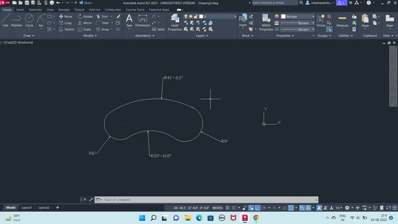
11.) This is the 9th and last Drawing which i'm going to plot here
Command Used : Line, Circle, Fillet, Trim
Procedure :
a.) Click on AutoCad icon on the top left side of screen, go to the new and then drawings
b.) Select Imperial from start from scratch option
c.) Go to the advance set-up
d.) Select Engineering as a unit
e.) Put 0'-0'' for precision
f.) Click next, and select Decimal Degrees
g.) Click next, Select Angle measure from East (0 will be for East) and click next
h.) Select angle direction, Counter Clockwise and click next
i.) Select Limits as 0'-0'', 0'-0'' and 12'-0'', 9',0''
j.) Select line tool, and draw a line of 32'-6"
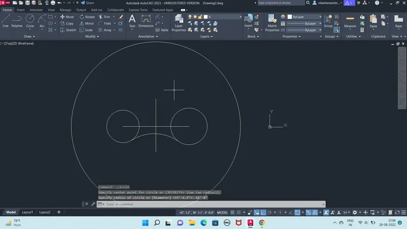
k.) Select Circle tool of radius 8'-0" on the LHS side of line
l.) Similarly, select Circle tool of radius 9'-0" on the RHS side of line
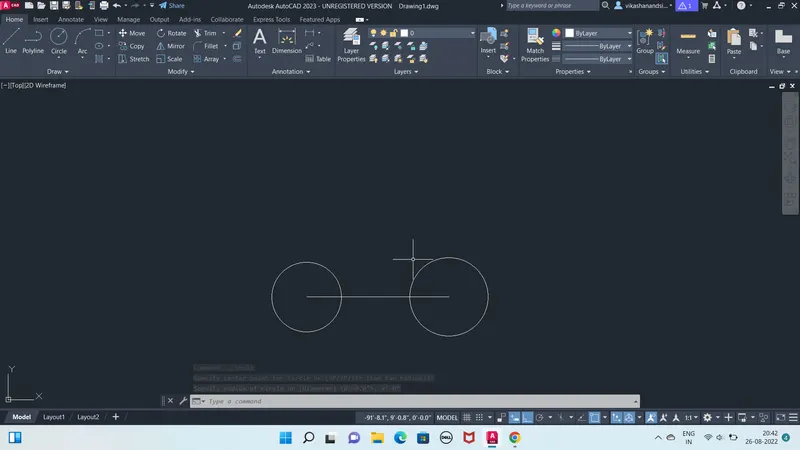
m.) Select Fillet option by typing in command bar, select radius of 32'-6" and click on both circles
n.) Select Circle tool of radius 41'-8" at the center of line and trim unwanted lines.
Result :