Creating a Floor plan, Footing detail and Isometric view using AutoCad
Ques : Creating a Floor plan, Footing detail and Isometric view using AutoCad.
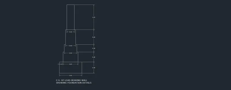
AIM :Cross section of load bearing wall
First will understand what is load bearing wall.
Load Bearing Wall : In this type of structures there are no any supportive columns hence all load from slab directly bear by walls. Wall is rest over plinth beam and plinth beam is connected with footing all around
Here i am explaining step by step procedure to draw this drawing.
Procedure : Write RECTANG in the command line to select rectangular tool , to start enter 1,1 as a starting point.
Next point will be @0.9, 0.45 to complete the rectangular shape.
Type dimension in command line select left top corner and enter value of 0.15 and than enter (Going in clockwise direction)
Select a line tool and click on 0.15 , and put a value of 0.45 in positive X Direction which is @0,0.45
Specify next point @0.05,0
Specify next point @0,0.30
Specify next point @0.05,0
Specify next point @0,0.60
Specify next point @0.05,0
Specify next point @0,1.00
Specify next point @0.3,0
Specify next point @0,-1.00
Specify next point @0.05,0
Specify next point @0,-0.6
Specify next point @0.05,0
Specify next point @0,-0.3
Specify next point @0.05,0
Specify next point @0,-0.4
Plotting is now done of structure , for showing dimensions select linear tool from annotation section and select both end of line to show dimension of each line of structure.
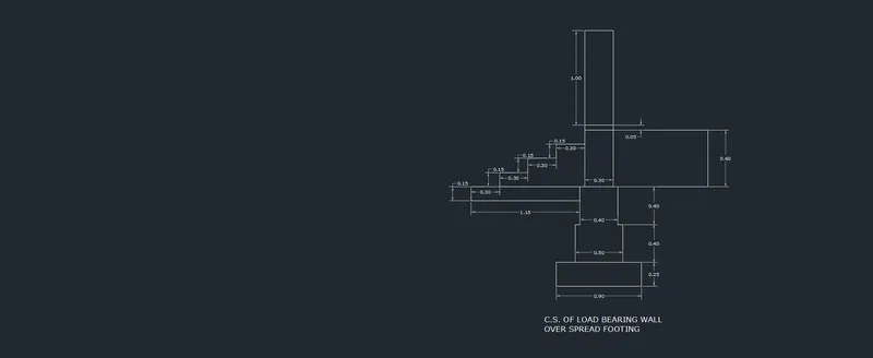
AIM : Cross Seciton of load bearing wall over spread footing
Procedure : Here is the step by step procedure to draw this drawing as mentioned below.
Write RECTANG in the command line to select rectangular tool , to start enter 1,1 as a starting point.
Next point will be @0.9, 0.25 to complete the rectangular shape.
Select a line tool and click on top left corner of rectangle, specify the next point as @0.2,0
Specify next point @0,0.40
Specify next point @0.05,0
Specify next point @0,0.40
Specify next point @0.05,0
Specify next point @0,0.6
Specify next point @0.3,0
Specify next point @0,-0.6
Specify next point @0.05,0
Specify next point @-0.40,0
Specify next point @0.05,0
Specify next point @-0.40,0
Specify next point @0.05,0
Now select line tool and click left top corner of 0.3x0.6 rectangular shape
Specify next point @0,0.05
Specify next point @0.3,0
Specify next point @-0.05,0
Now select line tool and click left top corner of 0.3x0.05 rectangular shape
Specify next point @0,1.00
Specify next point @0.3,0
Specify next point @-1.00,0
Now ,type offset in command bar and click on vertical line of 0.6 and put and unknown value 1m
Select line bar and join both points top & bottom direction (Right side of section)
Select a line tool and click on left top corner of rectangular shape 0.4x0.4
Specify next point @-1.15,0.00
Specify next point @0.00,-0.15
Specify next point @1.15,0.00
Select a line tool and click on left top corner of rectangular shape 1.15x0.15
Specify next point @0.3,0.00
Specify next point @0,0.15
Specify next point @0.3,0.00
Specify next point @0,0.15
Specify next point @0.3,0.00
Specify next point @0,0.15
Specify next point @0.3,0.00
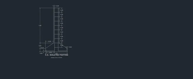
AIM : Cross Seciton of Isolated Footing
Procedure : Here is the step by step procedure to draw this drawing as mentioned below.
Select line tool and start with 1,1 coordinate
Specify next point @0,0.15
Specify next point @0.38,0.25
Specify next point @0,1.6
Specify next point @0.24,0
Specify next point @0,-1.6
Specify next point @0.38,-0.25
Now type DIM in command bar and select left topmost corner and type 0.04
Select a line tool and draw a line of length of 1.96 (-ve Y Dir) from the distance of 0.04 and specify the next point of @-0.38,0 and next line will be of @0.05,0 (L of bar)
Same to be done for RHS side reinforcement
Now draw a line b/w two 40mm covers which will later select as offset of length 160mm at the spacing of 200mm
Type offset in command bar and touch 160mm line , now enter the offset value of 0.2m and click downwords untill it reaches at bottom.
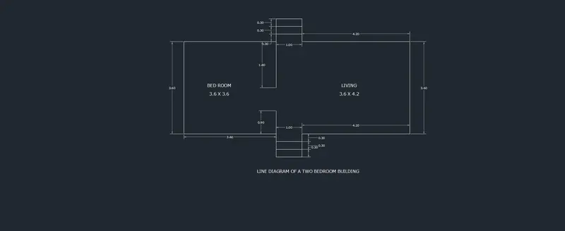
AIM :Layout of two bedroom Building
Procedure :
Plotting a diagram by using Relative rectangular coordinate method.
Here is the step by step procedure.
To select a line tool , write Line in command bar and specify starting coordinate as 1,1
Specify next point @0, 3.60
Specify next point @3.60,0
Specify next point @0, 0.30
Specify next point @1.00,0
Specify next point @0,-0.30
Specify next point @4.20, 0
Specify next point @0, -3.60
Specify next point @-4.20, 0
Specify next point @0, -0.30
Specify next point @-1.00, 0
Specify next point @0, 0.30
Specify next point @-3.60, 0
Now Click on the close option in command bar to close the loop.
Select a line tool and click on point @3.60,0 which is the second point
Press F8 for straight line
Enter the length of line as 1.80 and close it from the option in command bar
Similarly Select a line tool and click on point @0, 0.30 which is twelfth point , and enter the length of line as 0.90
This is now partition of both room
Now, Im drawing balance steps
For that i select offset tool and click on 1m line and put the offset value of 0.30 (For two times)
Now i select a line tool and join all offset points both side
Similarly i do with the bottom staircase.
AIM : To plot a drawing of Isomectric View of Steps
Procedure : To draw this i have to use isometric plane
Here are the following steps.
Move the cursor to isodraft icon , it has three option Isoplane left, Isoplane Top, Isoplane Right.
Select Isoplane Left from the option
Select Line tool by typing line in command bar.
Click on a point and move cursor in -ve X Direction and enter the Value 1
Now move cursor in +ve Y Direction and enter the value 0.15
Move cursor in +ve X Direction and enter the value 1
Move cursor in -ve Y Direction and enter the value 0.15
This the First RISER Drawn.
Now changing to Isoplane Top and clicking to the left top point for the drawing of TREAD
Select Line tool , enter the value 0.3 & enter (Moving cursor in Z Direction)
Moving cursor in -x Direction , putting value 1 and join the line
Hence the first step is drawn
Select Isoplane Left from the option
Select Line tool by typing line in command bar.
Click on a point and move cursor in -ve X Direction and enter the Value 1
Now move cursor in +ve Y Direction and enter the value 0.15
Move cursor in +ve X Direction and enter the value 1
Move cursor in -ve Y Direction and enter the value 0.15
This the Second RISER Drawn.
Now changing to Isoplane Top and clicking to the left top point for the drawing of TREAD
Select Line tool , enter the value 0.3 & enter (Moving cursor in Z Direction)
Moving cursor in -x Direction , putting value 1 and join the line
Hence the Second step is drawn
Repititing same process 3rd, 4th & 5th Riser and Tread.
Now to draw waist slab
Select Line tool and select Isoplane Top and move cursor in -ve X Direction and put value of 0.3
Join bottom tread point and top riser by using line command.

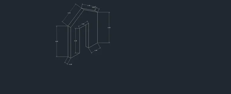
AIM : Draw Isometric View of Gabble Wall.
Procedure : To draw this i have to use isometric plane
Here are the following steps.
Move the cursor to isodraft icon , it has three option Isoplane left, Isoplane Top, Isoplane Right.
Select Isoplane Left from the option
Select Line tool by typing line in command bar.
Click on a point and move cursor in -ve X Direction and enter the Value 0.3
Now move cursor in +ve Y Direction and enter the value 3, Moving cursor in +X Direction and put 0.3 and move cursor downward. Select line 3 and connect it with loop
Now select Isometric Right ,select line command and click on first point and enter vaule 1 towards Rightside
Select Isoplane Left and select line tool and move cursor in upward direction enter 2.42 again select Isoplane right and select 1
Select isoplane left and select line tool and move cursor downwards put value 2.42 , move cursor in left direction and put 0.3 and join it to top line by putting nearest command in command bar.
This was the gate part now moving forward.
Again select Isoplane top and select line tool, put value 1 towards right side
Select Isoplane left ,select line tool,put value 3 towards upward direction.
Select left side of gabble wall corner , select line tool after selecting isoplane top and put 2.18 value towards right side, change plane to Isoplane left and move cursor downward put value 0.3 and connect the line.
Similarly repeat the same procedure for right side slope line which are 1.32 and 0.3 respectively.