Creation of geometries by Coordinate system methods using AutoCad
Ques. Create the geometries from P1 to P2 using all the coordinates system methods. You need to use the Line tool to create the geometries. Where required you need to use the circle tool.
Please read the drawings and find out the missing dimensions before working on the sketches.
Note: Use the Imperial Template and the Decimal Units to draft the features. Dimensions are there for
references
Answer
Aim : So in this challange i am going to create the geometries from P1 to P2 using all coordinated system methods which are Absolute, Relative and Direct distance entry method respectively.
Introduction : Coordinates are nothing but a number system which are used to represent exact position of point in the auto cad, like for example 0,0 which means Zero distance from X-Direction and Zero distance from Y-Direction and so on.
Types of Coordinate Systems.
1.) Absolute Coordinate System - Its a coordinate system in which entry always counts from origin which is (0,0)
2.) Relative Coordinate System - In this coordinate system, first point is always starts from origin (0,0) and then all successive positions are established with reference to the previous point in the autocad.
Relative Coordinate System is further classified into two more Coordinate System which are
i) Relative Rectangular Coordinates : In this coordinate system @ symbol used as instruction to count relative coordinates
for example @X,Y
ii) Relative Polar Coordinates : In this coordinate system < (less than sign) is used to represent angle which is followed by radial distance
for example, First point will be from origin (0,0), then next point will be @X<angle
3.) Distance Entry Method : In this entry method there is not required to put any symbol in command like @ and <
Its a very simple method in which line is drawn by pointing crusor in desired direction and simply putting distance in command bar as required.
Procedure :
Opening Auto Cad application
1.) Open a blank drawing file
2.) Put in the command 'STARTUP' and then enter, it will show enter the new value of startup, put 1
3.) Click on the Auto Cad icon on the top left side of screen and click NEW
4.) Select drawing from the create a new drawing
5.) On the screen it will show 'Start from scratch' option in which i select Imperial (Feet & Inches) from default settings.
6.) Click on advanced setup from the 'Use a Wizard'
7.) Now select Decimal unit from the Advance Setup
8.) Now select the Precision which starts from 0 and ends eight zeros after decimal.
9.) Now type Limit in command to set lower-left corner value 0,0 and upper-right corner 100,100 respectively.
Now Lets begin drafting different geometry as mentioned in drawing by different coordinates system.
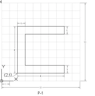
So, I will start drafting by using
1.) Absolute coordinate system
Here are the commands
1.) Type Line in command bar or just L to select the line tool.
2.) To start the line from origin that is (0,0) setting the first coordinate (2,1) which means Two tiles forward from X directoion and One tile upward from Y direction.
Now moving forward in anticlock wise direction
3.) Putting up next coordinate in command bar for point 2 is (8,1)
4.) Putting up next coordinate in command bar for point 3 is (8,2)
5.) Putting up next coordinate in command bar for point 4 is (3,2)
6.) Putting up next coordinate in command bar for point 5 is (3,6)
7.) Putting up next coordinate in command bar for point 6 is (8,6)
8.) Putting up next coordinate in command bar for point 7 is (8,7)
9.) Putting up next coordinate in command bar for point 8 is (2,7)
and then closing the loop by putting crusor on the first line and click on 'close' in command bar.

2.) Drafting by using Relative Rectangular Coordinate System.
1.) Type Line in command bar or just L to select the line tool.
2.) To start the line from origin that is (0,0) setting the first coordinate (2,1) which means Two tiles forward from X directoion and One tile upward from Y direction.
Now moving forward in anticlock wise direction
3.) Putting up next coordinate in command bar for point 2 is (@6,0) which means Six tiles forward towards X-direction with respect to previous point.
4.) Putting up next coordinate in command bar for point 3 is (@0,1)
5.) Putting up next coordinate in command bar for point 4 is (@-5,0)
6.) Putting up next coordinate in command bar for point 5 is (@0,4)
7.) Putting up next coordinate in command bar for point 6 is (@5,0)
8.) Putting up next coordinate in command bar for point 7 is (@0,1)
9.) Putting up next coordinate in command bar for point 8 is (@-6,0)
and then closing the loop by clicking 'close' in command bar.

3.) Drafting by using Relative Polar Coordinate System.
1.) Type Line in command bar or just L to select the line tool.
2.) To start the line from origin that is (0,0) setting the first coordinate (2,1) which means Two tiles forward from X directoion and One tile upward from Y direction.
Now moving forward in anticlock wise direction
3.) Putting up next coordinate in command bar for point 2 is (@6<0) which means Six tiles forward towards X-direction with respect to previous point and angle is Zero
4.) Putting up next coordinate in command bar for point 3 is (@1<90)
5.) Putting up next coordinate in command bar for point 4 is (@5<180)
6.) Putting up next coordinate in command bar for point 5 is (@4<90)
7.) Putting up next coordinate in command bar for point 6 is (@5<0)
9.) Putting up next coordinate in command bar for point 7 is (@1<90)
10.) Putting up next coordinate in command bar for point 8 is (@6<180)
and then closing the loop by clicking 'close' in command bar.
4.) Drafting by using Direct Distance Entry System.
1.) Type Line in command bar or just L to select the line tool.
2.) To start the line from origin that is (0,0) setting the first coordinate (2,1) which means Two tiles forward from X directoion and One tile upward from Y direction.
3.) Now for the 2nd point, enter length as 6
4.) For the 3rd point, enter length as 1
5.) For the 4th point, enter length as 5
6.) For the 5th point, enter length as 4
7.) For the 6th point, enter length as 5
8.) For the 7th point, enter length as 1
9.) For the 8th point, enter length as 6
and then closing the loop by clicking 'close' in command bar.
Now coming to the 2nd Plotting which is P2
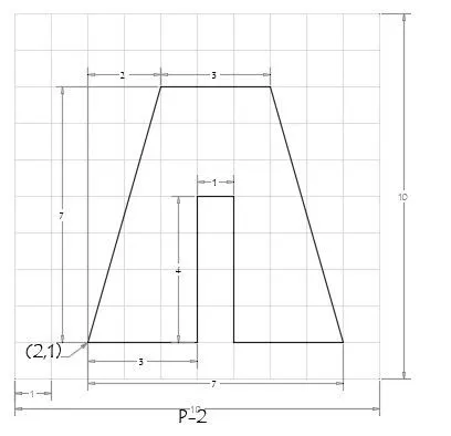
1.) Absolute coordinate system
Here are the commands
1.) Type Line in command bar or just L to select the line tool.
2.) To start the line from origin that is (0,0) setting the first coordinate (2,1) which means Two tiles forward from X directoion and One tile upward from Y direction.
Now moving forward in anticlock wise direction
3.) Putting up next coordinate in command bar for point 2 is (5,1)
4.) Putting up next coordinate in command bar for point 3 is (5,5)
5.) Putting up next coordinate in command bar for point 4 is (6,5)
6.) Putting up next coordinate in command bar for point 5 is (6,1)
7.) Putting up next coordinate in command bar for point 6 is (9,1)
8.) Putting up next coordinate in command bar for point 7 is (7,8)
9.) Putting up next coordinate in command bar for point 8 is (4,8)
and then closing the loop by putting crusor on the first line and click on 'close' in command bar.

2.) Drafting by using Relative Rectangular Coordinate System.
1.) Type Line in command bar or just L to select the line tool.
2.) To start the line from origin that is (0,0) setting the first coordinate (2,1) which means Two tiles forward from X directoion and One tile upward from Y direction.
Now moving forward in anticlock wise direction
3.) Putting up next coordinate in command bar for point 2 is (@3,0) which means Three tiles forward towards X-direction with respect to previous point.
4.) Putting up next coordinate in command bar for point 3 is (@0,4)
5.) Putting up next coordinate in command bar for point 4 is (@1,0)
6.) Putting up next coordinate in command bar for point 5 is (@0,-4)
7.) Putting up next coordinate in command bar for point 6 is (@3,0)
8.) Putting up next coordinate in command bar for point 7 is (@-2,7)
9.) Putting up next coordinate in command bar for point 8 is (@-3,0)
and then closing the loop by clicking 'close' in command bar.
3.) Drafting by using Relative Polar Coordinate System.
1.) Type Line in command bar or just L to select the line tool.
2.) To start the line from origin that is (0,0) setting the first coordinate (2,1) which means Two tiles forward from X directoion and One tile upward from Y direction.
Now moving forward in anticlock wise direction
3.) Putting up next coordinate in command bar for point 2 is (@3<0) which means Three tiles forward towards X-direction with respect to previous point and angle is Zero
4.) Putting up next coordinate in command bar for point 3 is (@4<90)
5.) Putting up next coordinate in command bar for point 4 is (@1<0)
6.) Putting up next coordinate in command bar for point 5 is (@4<270)
7.) Putting up next coordinate in command bar for point 6 is (@3<0)
9.) Putting up next coordinate in command bar for point 7 is (@7<106)
10.) Putting up next coordinate in command bar for point 8 is (@3<180)
and then closing the loop by clicking 'close' in command bar.
4.) Drafting by using Direct Distance Entry System.
1.) Type Line in command bar or just L to select the line tool.
2.) To start the line from origin that is (0,0) setting the first coordinate (2,1) which means Two tiles forward from X directoion and One tile upward from Y direction.
3.) Now for the 2nd point, enter length as 3
4.) For the 3rd point, enter length as 4
5.) For the 4th point, enter length as 1
6.) For the 5th point, enter length as 4
7.) For the 6th point, enter length as 3
8.) For the 7th point, enter length as 7.61 by using square root of (3)^2 + (7)^2 (by enabling polar tracking by using F8)
or enter the length 7 in command bar at angle of 106 degree (by enabling polar tracking by using F8)
9.) For the 8th point, enter length as 3
and then closing the loop by clicking 'close' in command bar.
Now coming to the another plotting which is P-4
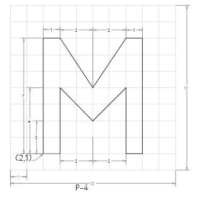
1.) Absolute coordinate system
Here are the commands
1.) Type Line in command bar or just L to select the line tool.
2.) To start the line from origin that is (0,0) setting the first coordinate (2,1) which means Two tiles forward from X directoion and One tile upward from Y direction.
Now moving forward in anticlock wise direction
3.) Putting up next coordinate in command bar for point 2 is (3,1)
4.) Putting up next coordinate in command bar for point 3 is (3,5)
5.) Putting up next coordinate in command bar for point 4 is (5,3)
6.) Putting up next coordinate in command bar for point 5 is (7,5)
7.) Putting up next coordinate in command bar for point 6 is (7,1)
8.) Putting up next coordinate in command bar for point 7 is (8,1)
9.) Putting up next coordinate in command bar for point 8 is (8,8)
10.) Putting up next coordinate in command bar for point 9 is (7,8)
11.) Putting up next coordinate in command bar for point 10 is (5,5)
12.) Putting up next coordinate in command bar for point 11 is (3,8)
13.) Putting up next coordinate in command bar for point 11 is (2,8)
and then closing the loop by putting crusor on the first line and click on 'close' in command bar.

Now plotting P-5 by using relative rectangular coordinate system
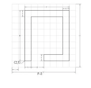
Now, i am going plot this drawing by using relative rectangular coordinate method.
1.) Select line tool by typing Line in command bar
2.) Enter 2,1 as a first point
3.) Enter @1,0 as second point
4.) Enter @0,7 as third point
5.) Enter @5,0 as forth point
6.) Enter @0,-6 as fifth point
7.) Enter @-3,0 as sixth point
8.) Enter @0,-1 as seventh point
9.) Enter @4,0 as eight point
10.) Enter @0,8 as ninth point
11.) Enter @-7,0 as tenth point
Select close option from command bar

Now coming to the another plot P-7 using absolute coordinate system.
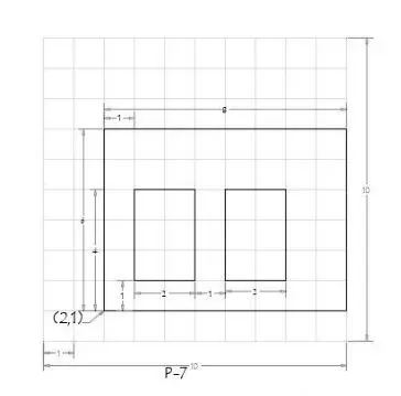
Type line in command bar to select the line tool
1.) Starting from coordinate (2,1) as a 1st point
2.) Type 10,1 in command bar for 2nd point
3.) Type 10,7 in command bar for 3rd point
4.) Type 2,7 in command bar for 4th point
5.) Now select close option in command bar to close the loop
6.) Select line tool and type 3,2 for 1st point inside the box
7.) Type 5,2 in command bar for 2nd point
8.) Type 5,5 in command bar for 3rd point
9.) Type 3,5 in command bar for 4th point
Now select close option in command bar to close the loop
10.) Select line tool and type 6,2 for 1st point inside the box
11.) Type 8,2 in command bar for 2nd point
12.) Type 8,5 in command bar for 3rd point
13.) Type 6,5 in command bar for 4th point
Now select close option in command bar to close the loop

Coming to the next plot P-8, by using absolute coordinate system.
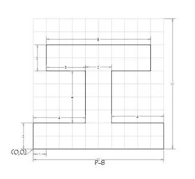
Select line tool by typing line in the command bar
1.) Put 0,0 as a 1st point
2.) put 10,0 as a 2nd point
3.) put 10,2 as a 3rd point
4.) put 6,2 as a 4th point
5.) put 6,6 as a 5th point
6.) put 9,6 as a 6th point
7.) put 9,8 as a 7th point
8.) put 1,6 as a 8th point
9.) put 4,6 as a 9th point
10.) put 4,2 as a 10th point
11.) put 0,2 as a 11th point, close the loop by selecting close option in command bar.

Now coming to the another plot which is P-9, Drawing in autocad by using absolute coordinate system.
Select line tool
Start first point by typing 1,1 in command bar
For 2nd point 5,1
For 3rd point 5,3
For 4th point 3,3
For 5th point 3,2
For 6th point 2,2
For 7th point 2,4
For 8th point 5,4
For 9th point 5,6
For 10th point 1,8 and then close the loop by selecting close option from command line.
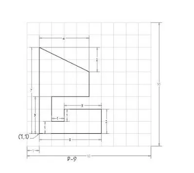

Here is the another plot which i am going to draw in autocad by using Absolute coordinate system method.
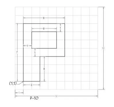
Select line tool by typing Line in command bar
For first point to start the plot put 1,1
2nd point will be 3,1
3rd point will be 3,4
4th point will be 6,4
5th point will be 6,8
6th point willl be 1,8
Close the loop by selecting close option in command line
Again select line from command line
First point for that will be 2,7
2nd point will be 5,7
3rd point will be 3,5
4th point will be 2,5 and close the loop

Now coming to the next part.
(B)Civil Related Problems
Draw the profile and the trusses using any coordinate system methods. The dimensions are there for references.
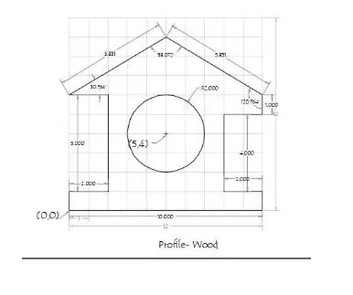
I am going to plot this by using Relative Polar coordinate system & Direct Distance entry method
Starting from clock-wise direction
1.) Type Line in command bar or just L to select the line tool.
2.) First point of plot will start from origin (0,0) i.e Zero distance from X & Y direction respectively.
3.) Now for the 2nd point, enter length as 1 towards positive Y direction
4.) For the 3rd point, enter length as 2 towards positive X direction
5.) For the 4th point, enter length as 5 towards positive Y direction
6.) For the 5th point, enter length as 2 towards negative X direction
7.) For the 6th point, enter @5.831<30.964 (Polar tracking on)
8.) For the 7th point, enter @5.831<329.036 (Polar tracking on)
9.) For the 8th point, enter @1<270 (Polar tracking on) towards negative Y direction
10.) For the 9th point, enter length as 2 towards negative X direction
11.) For the 10th point, enter length as 4 towards negative Y direction
12.) For the 11th point, enter length as 2 towards positive X direction
13.) For the 12th point, enter length as 1 towards negative Y direction
13.) For the 13th point, enter length as 10 towards negative X direction
Click close option in command bar to close the loop
Now type circle in command bar and put (5,4) for its position from origin as a centre point.
For drawing a circle enter 2 for radius.

Now coming to the next profile for plotting
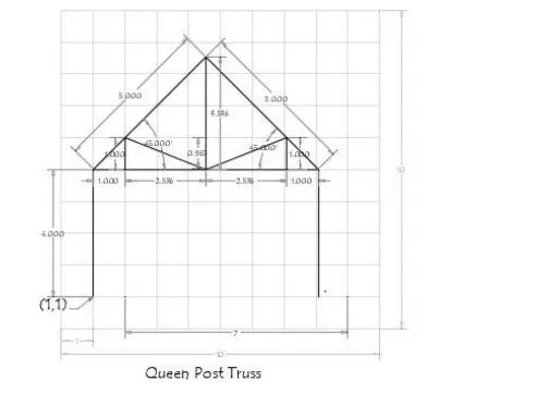
I am going to plot this by using relative polar coordinate method & Direct Distance entry method
Starting from clock-wise direction
1.) Type Line in command bar or just L to select the line tool.
2.) To specify first point type 1,1 in command bar
3.) For the 2nd point, enter @4<90
4.) For the 3rd point, enter @5<45
5.) For the 4th point, enter @5<315
5.) For the 5th point, 4<270
6.) Now close the line tool by clicking close option in command bar
7.) Select a line tool & go to the point 4th point and enter @1<180 which is 6th point
8.) For the 7th point enter @2.536<180
9.) For the 8th point enter @2.536<180
10.) For the 9th point enter @1<180 and close the loop by clicking on close option in command bar
11.) Select a line tool and and click on point 8th and enter @1<90 (point 9) similarly go to the 5th point and enter @1<90 (point 10)
12.) Select a line tool and Go to the point 7 and enter @3.536<90 (point 11)
13.) Select a line tool and join Point 9 and Point 7 by keeping polar tracking mode on similrly join line tool Point 10 & point 7 and close the loop

Now coming to the last plot, which im gonna draw by using absolute coordinate system.
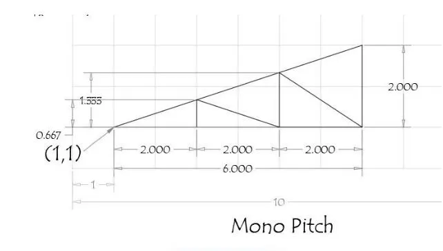
Select line tool by typing Line in command bar.
1.) For the 1st point , enter 1,1 in command bar
2.) For the 2nd point, enter 3,1 in command bar
3.) For the 3rd point, enter 5,1 in command bar
4.) For the 4th point, enter 7,1 in command bar
5.) For the 5th point, enter 7,3 in command bar
6.) Now join the first point by keeping polar tracking mode on and close the loop
7.) Select line tool and move cursor near point 2, and join it on tangent line (6th point) similarly join to 3rd point (7th point) and join it on tangent line (8th point)