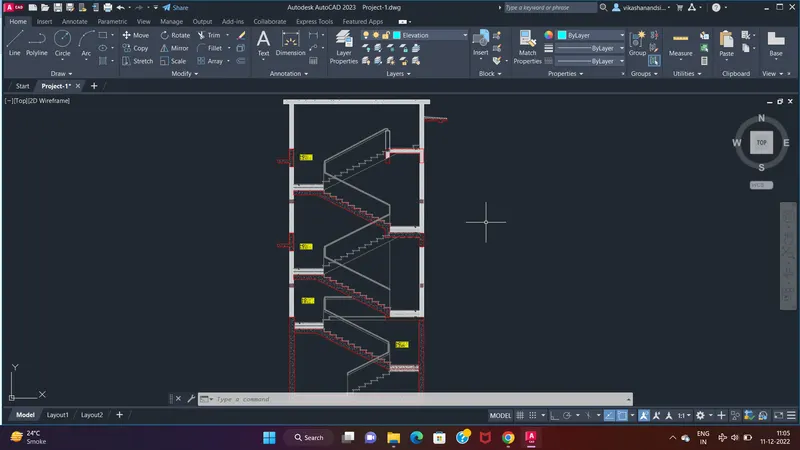
Project 1 _Creating an Architectural plan for the provided plot size and develop relevant basic structural drawings
AIM : Design and Draft a layout of a residential building with the following details:
a. Plot Size: 60’x20’(18.3m x6m)
b. Orientation- Facing East
c. Develop the following: 1. Architectural Drawing (Floor Plan, Elevations, and Sections) 2. Structural Drawing (Column, Bean, Footing Plan)
ANSWER :
First of all I will start with drawing a Plan. Plan will be of G+2 residencial building having same room sizes on all floors.
There will be a mumty for staircase and roof plan to show brickbat waterproofing with slope of 1:20
Apart from that ill draw Footing & Column layout plan, Plint beam Layout Plan, Roof beam layout plan
Later on i will draw Elevation of building and section drawing for staircase.
So, here is the list of Architectural & Structural Drawings.
Architectural Drawings
Floor Plans (Ground to 2nd floor)
Terrace Waterproofing Plan
Elevation Plan (only east facing)
Structural Drawings
Column & Footing Layout
Plinth Beam Layout
Floor Beam Layout
Sections.
LEGENDS:
Main Wall -230mm
Partition Wall - 110mm
Windows- 1m x 1m
Doors- 1m x 2.4m
Columns - 400 x 300mm
Plinth Beam Width - 1.) 400mm 2.) 300mm (Common depth of 600mm)
Slab Thickness - 150mm
Chajja Thickness - 150/100 (Tapered)
Floor Beam Width - 1.) 400mm 2.) 300mm (Common depth of 400mm)
Staircase Riser-150mm, Tread - 300mm
Mumty Slab - 150mm Thickness
Terrace Waterproofing Slope - 1:20
Command Used :
1. XLINE
2. Offset
3. Trim
4. Fillet
5. Circle
6. Tool paletts
7. Design Center
8. Hatch
9. Match Properties
10. Dimensions
11. Texts
12. Mirror
Procedure :
Select XLine by typing in command bar, put the value of length & Width
Take offset of 0.23m for external walls, trim Unwanted lines.
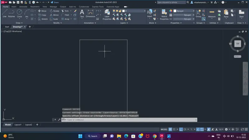
Now drawing partition lines of bedrooms.
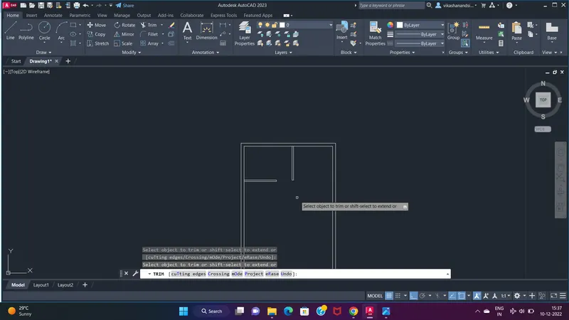
Now, Drawing partition walls for toilets by taking offset of 0.11m
Now plotting Columns, of size 0.4 x 0.3 m
Selecting mirror from command and applying by selecting partition walls of bedroom & toilets
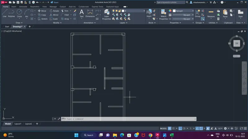
Now, selecting line tool from command bar and drawing lines for staircase.
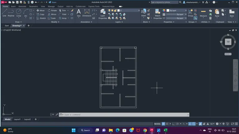
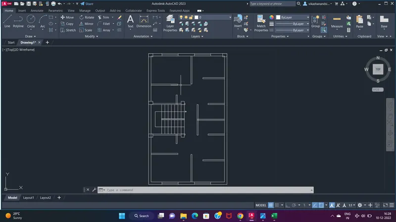
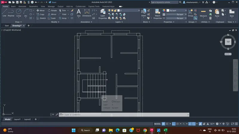
Now, by using line tool, drawing hinges for doors.
By using Circle tool drawing arc for door opening.
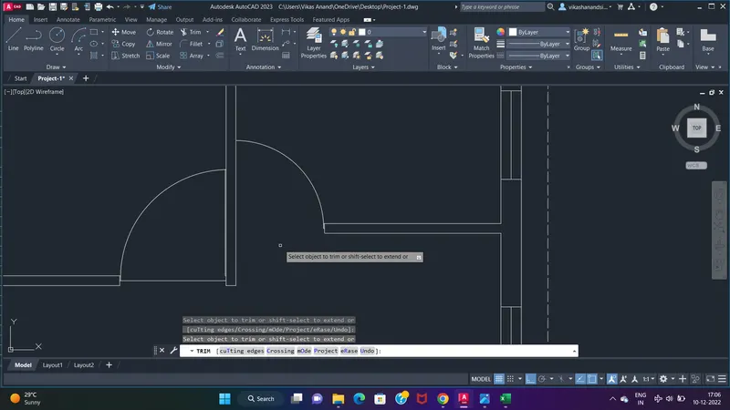
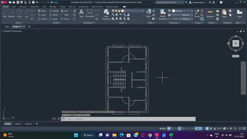
Now, trimming unwanted lines.
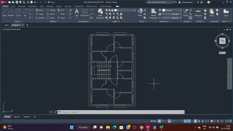
Now, Select text from command bar and start naming rooms.
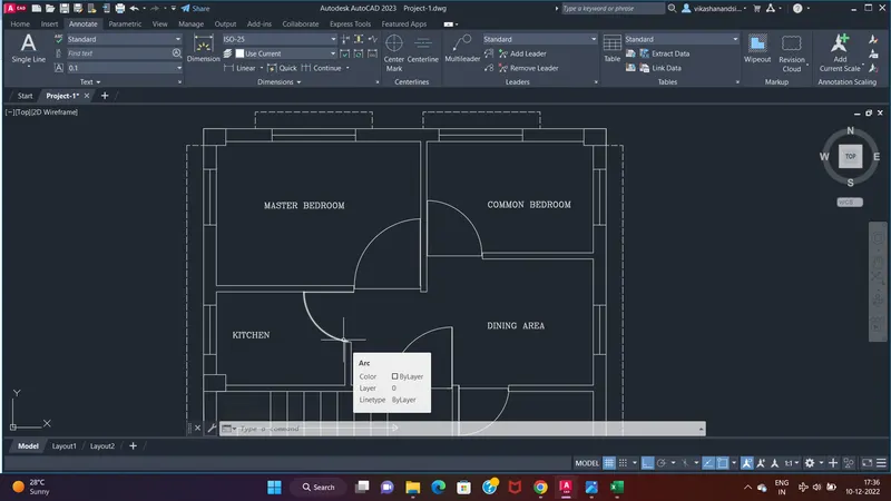
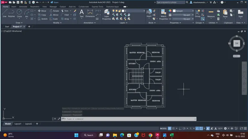
Now, go to the Layer Properties and start adding all element which were used in layout.
Now Selecting all doors and putting in layer, here it is
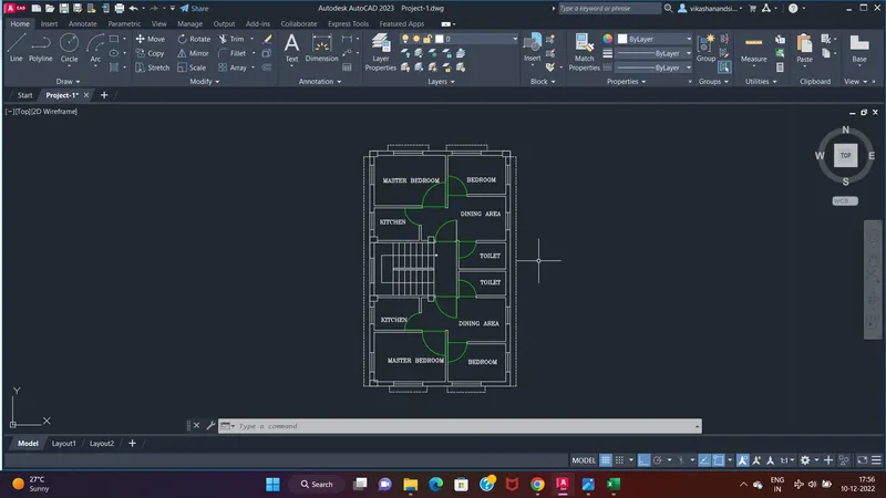
Now, Putting Texts in Layers, Windows & Chajja in different layers.
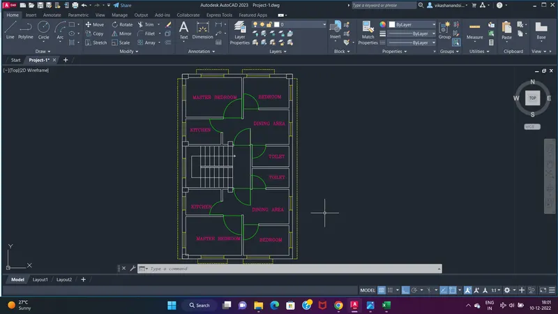
Now Staircase in Different layer.
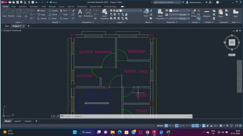
Here as you can see there are different elements of drawing in different layers.
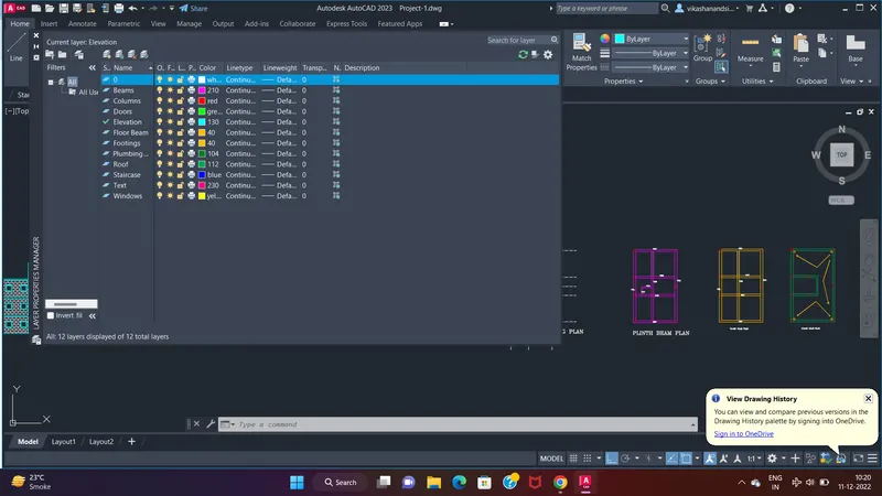
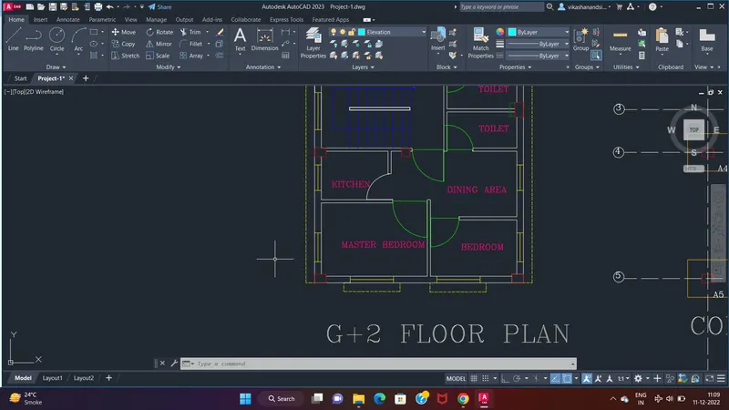
Here is the plan ready for G+2 Floor Residencial Building
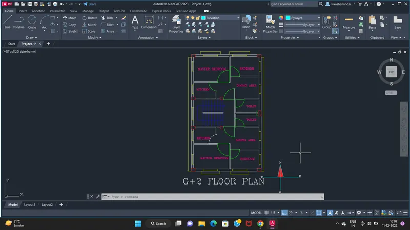
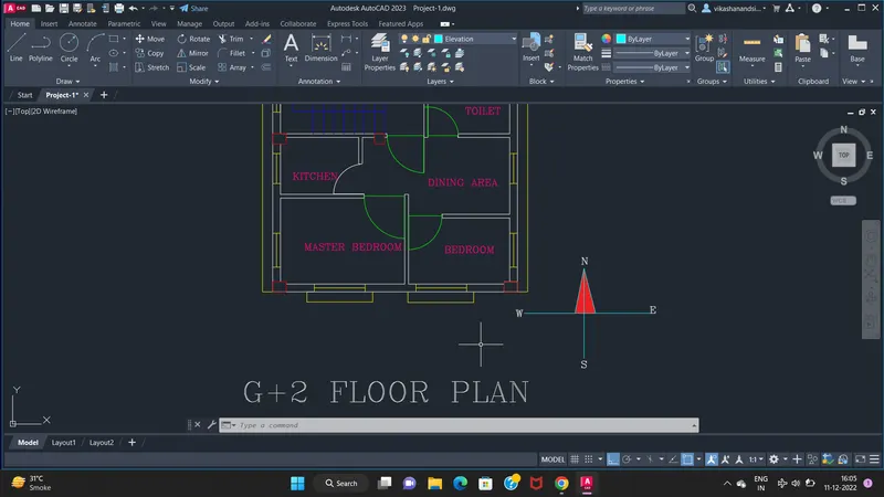
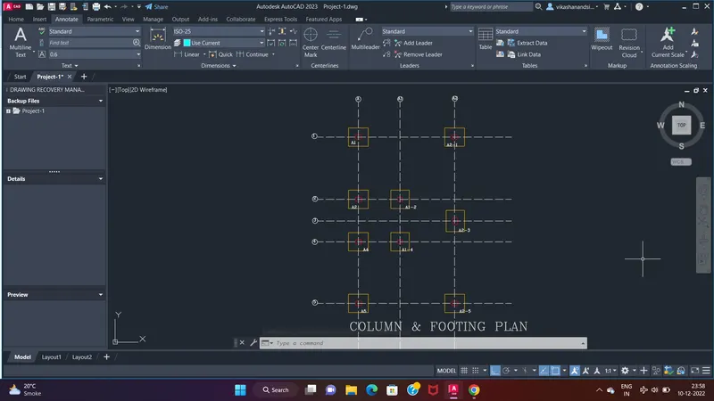
Now, first of all i will copy floor plan and trim off all lines except column.
Now ill take offset of 500mm from all sides of column and i will use fillet option to make it rectangular.
Selecting Line tool and bisecting perpendicularly off all columns in a row & column to make grid line.
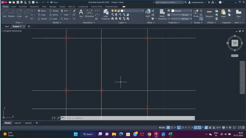
Now, seleting line and changing its shape by reducing scale to 0.005m from properties of Line.
To change line in dash form selecting ADASISO00 from Line properties.
Here is the Column & Footing Layout Ready.
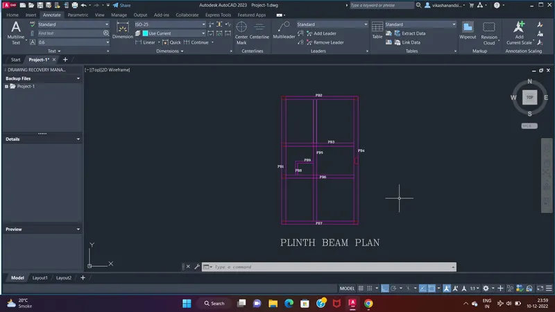
Now, Copying floor layout and removing all internal walls including doors & windows. We have only columns left on screen.
Selecting line tool and joining all columns through line which represents nothing but Plinth Beams.
Width of plinth beams is of 300mm & 400mm respectively.
Adding two more beams for staircase slab dowels.
Now, Selecting Text tool to name all Plinth Beams as PB1 etc.
Here is the Plinth Beam Layout Ready.
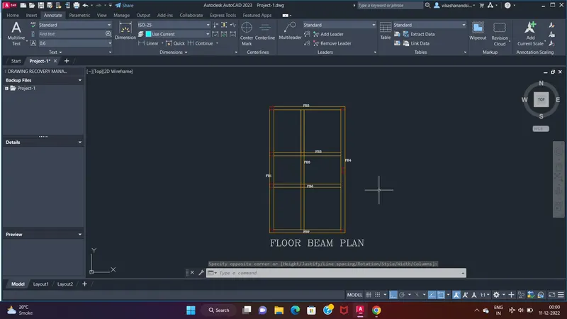
Once again i will copy same plinth beam layout and changing the name as FB (Floor Beams)
Because width and reinforcement will be same as plinth beam.
Now opening Layer properties and adding one more row for Floor Beam and also changing colour to look differently.
Here is the Floor Beam Plan Ready.
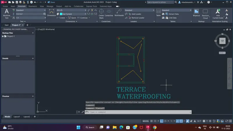
Now, copying floor plan one more time are removing all internal lines and doors windows to show Roof, Now selecting Line tool to represent slope.
Selecting Circle tool of 100mm dia and placing at all corners of building to represent rain water pipe cutout.
Here is the Terrace Waterproofing Plan is Ready.
Now Selecting line tool and drawing first line of which length will be a width of East side facing building.
Taking offset by using offset tool to show floors, roof section of 0.15m slab, columns etc.
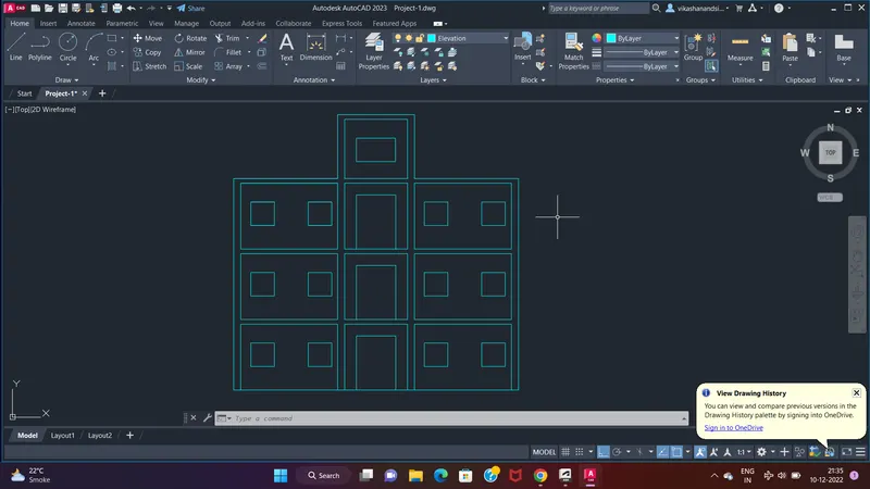
Now, Selecting line tool to draw lintel band of 0.1m thick for windows & doors opening.
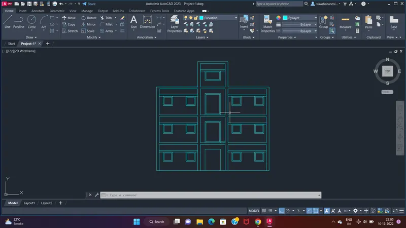
Not, Selecting Hatch tool and selecting internal area of Brick wall.
Changing scale to 0.05m
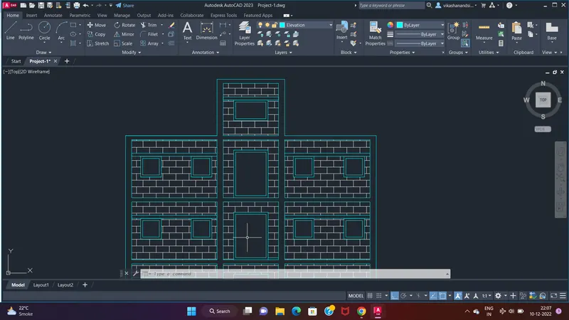
Now, Selecting Tool Pallete tool by typing in command bar ,from architecture section select door and giving it color by using hatch command.
By the using Hatch command, selecting window area for Gost Glass hatching.
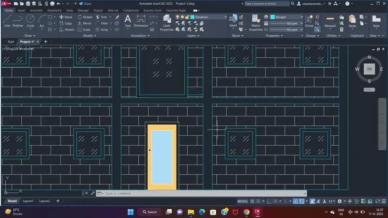
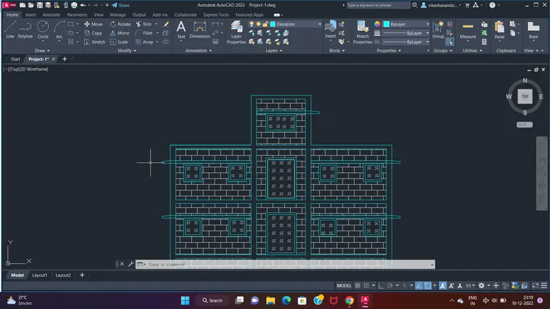
Here is the Elevation ready of East Facing Building
Now Selecting Line tool and drawing steps of staircase having riser of 0.15m and 0.3m
Proving chajja for Window in mumty.
Staircase wall of 0.23m width and RCC Slab of Mumty of 0.15m thickness.
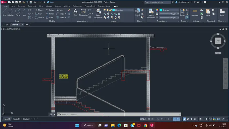
Here is the Staircase ready.