Drafting of various geometries using Chamfer, Fillet tool in AutoCad
AIM:
The aim is to draft various geometries using chamfer, fillet tool in AutoCAD and provide the procedure along with it.
INTRODUCTION:
Chamfer - It is a tool used in AutoCAD that creates diagonal edges on the selected sides. It can be selected from the modify ribbon or by typing chamfer on the command bar.
Fillet - It is a tool used in AutoCAD to create a rounded edge between two lines that may or may not be intersecting. It can be selected from the modify ribbon or by typing fillet on the command bar.
Trim - It is a tool used in AutoCAD to remove the excess lines or parts of object without entirely removing the object or the line. It is one of the most commonly used tools in AutoCAD.
Rotate - This tool is used to rotate the selected object or line in the specified direction. This can be selected from the ribbon with the rotate icon or by typing rotate in the command box
PROCEDURE:
Figure 1 -
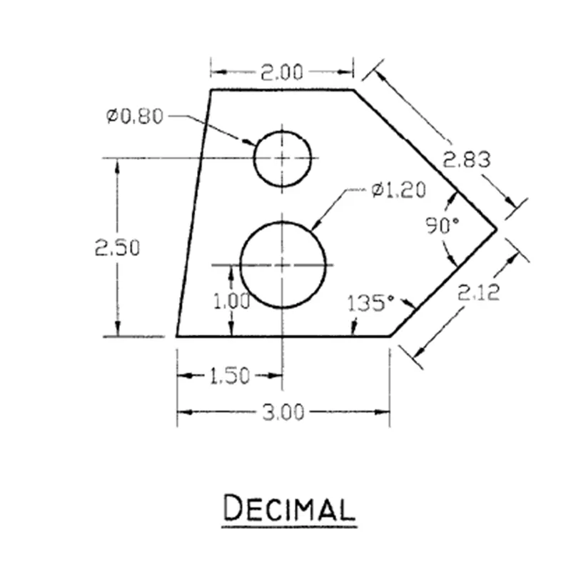
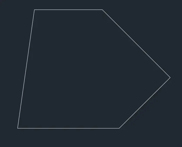
- Draw a line of length 3 units and from the right end, draw another line of length 2.12 at 45 degrees from the x-axis.
- From the last line, draw a line of length 2.83 at 90 degrees from the previous line. From there draw a line of length 2 units. Then select close.
- From the left bottom corner, at a distance of 1.5 on the x-axis and at a distance of 1 on the y-axis, draw a circle with a diameter of 1.2.
- From the left bottom corner, at a distance of 1.5 on the x-axis and at a distance of 2.5 on y-axis, draw a circle with diameter of 0.8
RESULT:
The figure is drawn and is shown below.
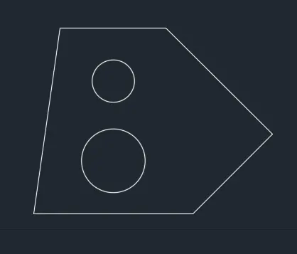
Figure - 2
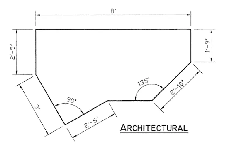
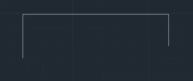
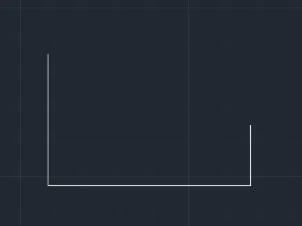
- Draw a line of length 8'. From the left end, draw a line of length 2'5" downwards.
- From the right end, draw a line of length 1'9" downwards.
- From here, draw a line of length 2'10" at an angle of 225 degrees from the x-axis. Then draw it further towards left.
- from the left end, draw a line of length 3 units downwards and then another line of 2'6" rightwards.
- Rotate the last two lines at an angle that joins with the previous line. Then trim the extra line after intersecting.
RESULT:
The figure is drawn and is shown below.
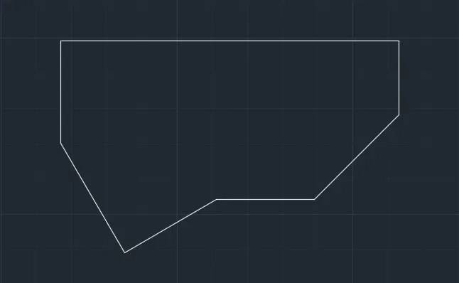
Figure - 3
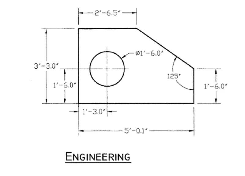
Draw a line of length 5'0.1". From the left end, draw a line of length 3'3" upwards. From there, draw a line of length 2'6.5" rightwards.
From the right end, draw a line of length 1'6" upwards and then join it with the previous line.
- At a distance of 1'3" from the x-axis and 1'6" from the y-axis, draw a circle of diameter 1'6"
RESULT:
The figure is drawn and is shown below.
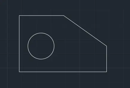
Figure - 4
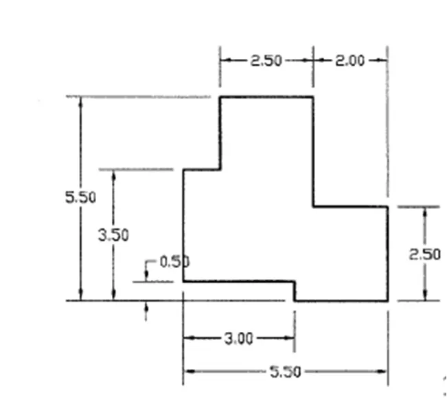
- Select polyline command. Draw line of length 2.5 upwards, then 2 in leftwards, again 3 in upwards.
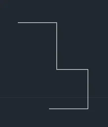
- Then 2.5 in leftwards. After that 2 in downwards. Then 1 in leftwards. Again 3 in downwards.
- Then 3 in rightwards and 0.5 in downwards and click on Close.
RESULT:
The figure is drawn and is shown below.
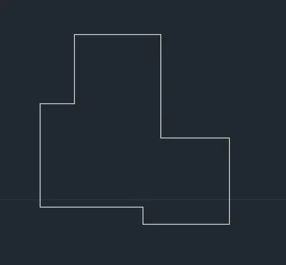
Figure - 5
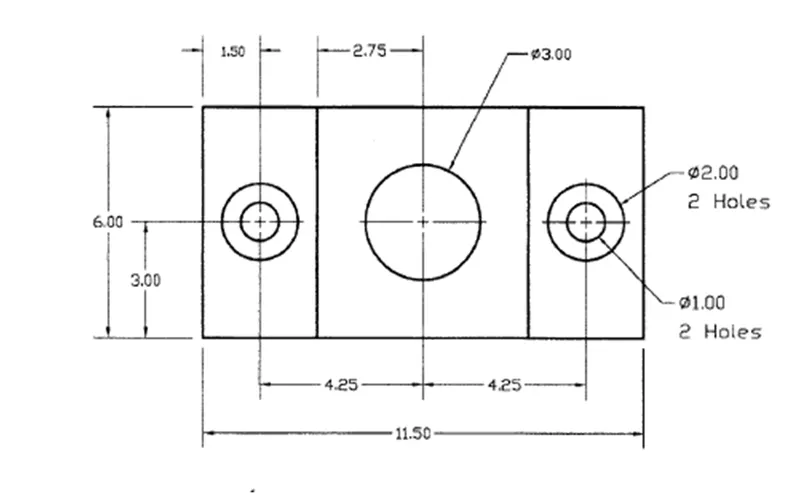
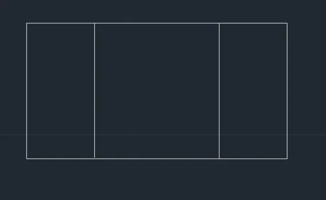
- Draw a rectangle of length 11.5 and width 6. Draw two lines of length 6 vertically from a distance of 3 from both ends of the rectangle.
- From the centre of the rectangle draw a circle of diameter 3
- From a distance of 1.5 in the x-axis and 3 in the y-axis, draw two circles of diameters 1 and 2.
- From a distance of 10 in the x-axis and 3 in the y-axis, draw two circles of diameters 1 and 2.
RESULT:
The figure is drawn and is shown below.
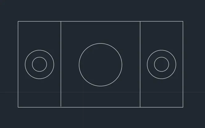
Figure - 6
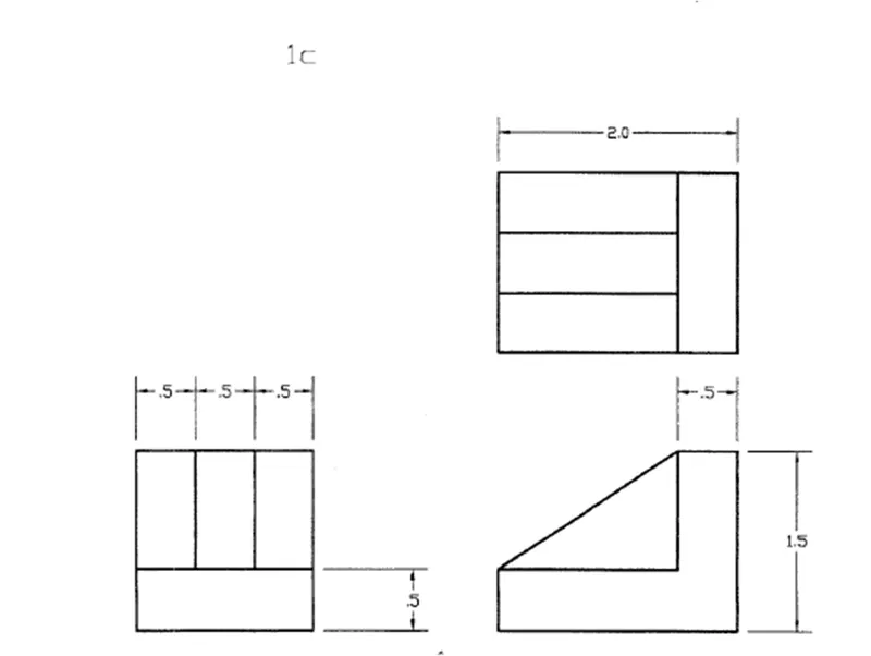
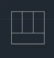
- Draw a square of size 1.5 x 1.5
- Draw a line of length 1.5 from 0.5 distance from the lower line of the square.
- Draw two lines of length 1 at a distance of 0.5 from each other.
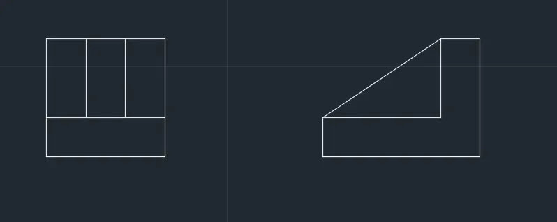
- Draw a line of length 2 horizontally. From the right end, draw a line of length 1.5 upwards and a line of length 0.5 leftwards.
- From here, draw a line of length 1 downwards and another line of length 1.5 leftwards and then a line of 0.5 downwards.
- Now join the two corners using line.
- Above the previous diagram, draw a rectangle of length 2 and width 1.5
- Draw a line of length 1.5 from 0.5 distance from right end vertically.
- Draw two lines of length 1.5 at a distance of 0.5 from each other horizontally.
RESULT:
The figure is drawn and is shown below.
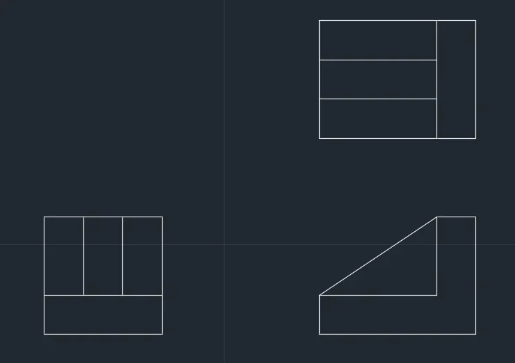
Figure - 7
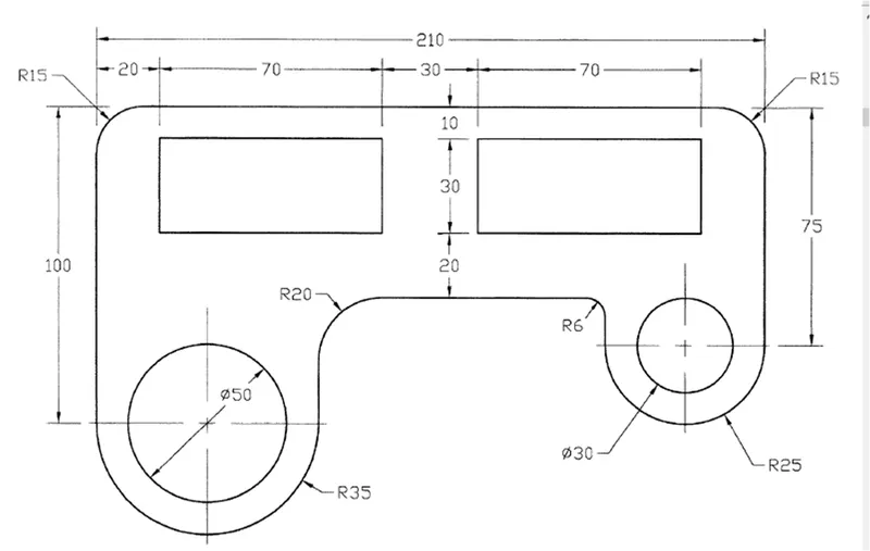
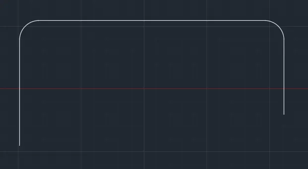
- Draw a line of length 210 units. From the left end, draw a line of length 100 units.
- From the right end, draw a line of length 75 units.
- Using fillet command, select radius 15 and curve both corners.
From the left line, draw an arc of radius 35 and a circle of radius 25. From the arc, draw the line upwards
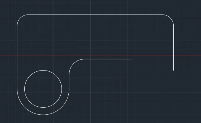
- From the right end of the line, draw an arc of radius 25 and a circle of radius 15. From the arc draw the line upwards.
- Join the two lines and fillet both. Use radius of 20 units for left corner fillet and radius of 6 units for right corner fillet.
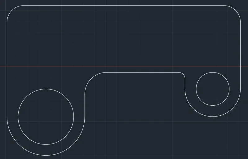
- Draw two rectangles of length 70 units and width 30 units. The distance of the rectange edge is 20 units from the left side for left rectangle.
- Similarly the distance of the rectange edge is 20 units from the right side for right rectangle.
RESULT:
The figure is drawn and is shown below.
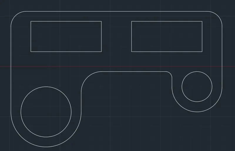
Figure - 8
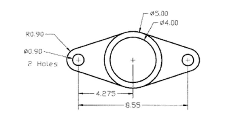
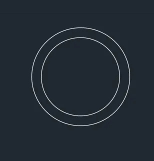
- Draw two circles with the same centre and different diameters of 4 units and 5 units.
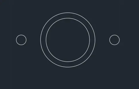
- Draw another two circles from a distance of 4.275 from either sides of the centre of the first circle with diameter 0.9
- Draw two arcs on left side of left circle and on the right side of the right circle. with centre being the same as that of the circle with a radius of 0.9 units
- Draw a line by selecting the tangent option and specify the first point in the arc and the second point in the circle. Repeat this in both up and down direction of both left and right side arcs.
- Using the trim command trim off the excess lines.
RESULT:
The figure is drawn and is shown below
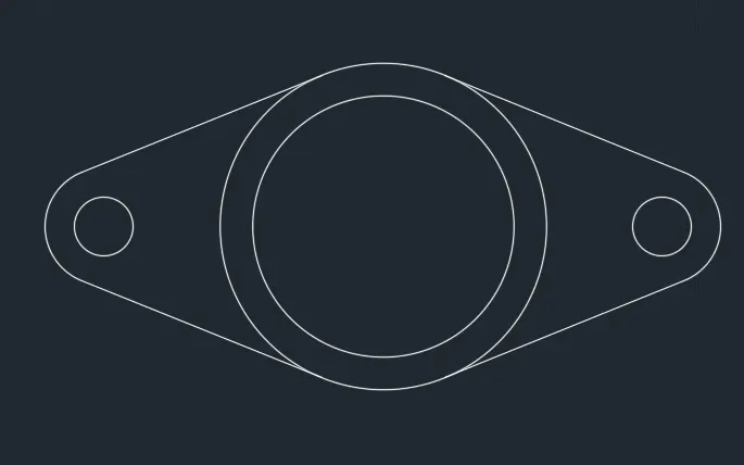
Figure - 9
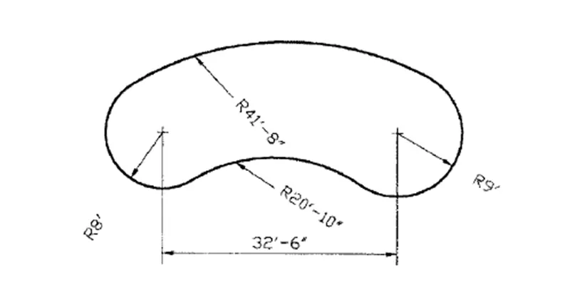
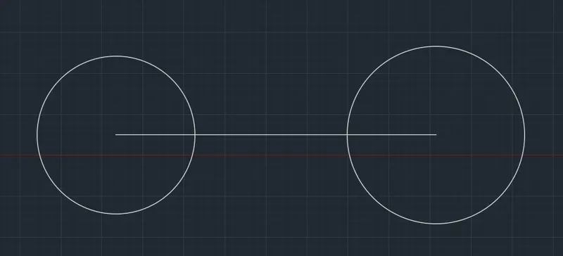
- Draw two circles of radius 8' and 9' with centre at a distance of 32'6" from each other.
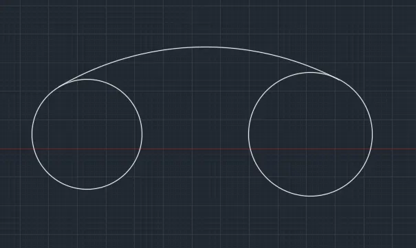
- Draw a circle using tangent-tangent-radius option. Specify the two circles as tangent surface and enter radius of 41'8"
- Draw a circle using tangent-tangent-radius option. Specify the two circles as tangent surface and enter radius of 20'10"
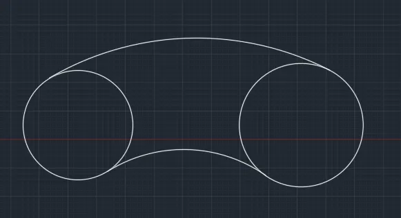
- Using trim command, trim off the excess lines from the figure
RESULT:
The figure is drawn and is shown below
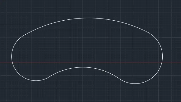
Figure - 10
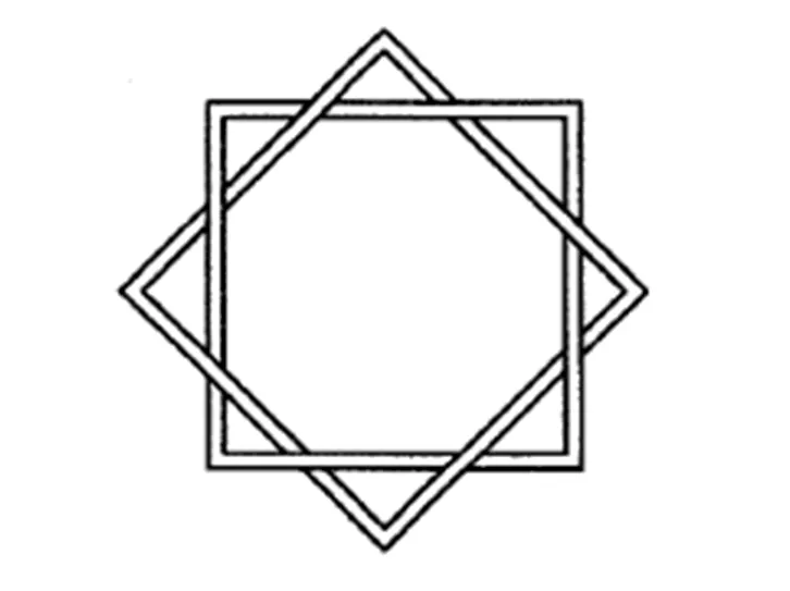
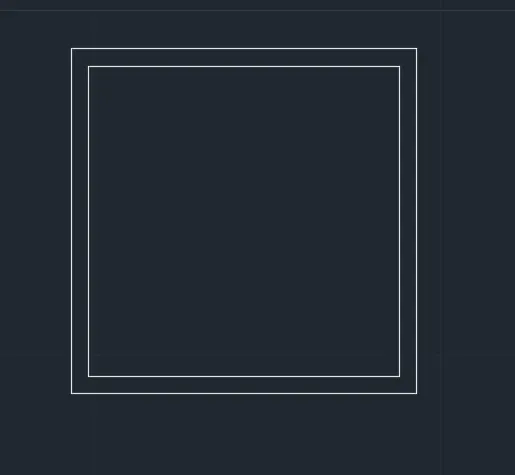
- Using rectangle command, draw a square of any desired unit (here 10)
- Using offset command, offset the square by 0.5 units
- Select rotate command and select the object. Select copy option and rotate the object by 45 degrees
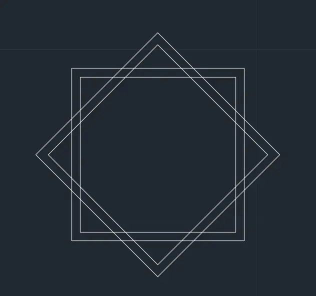
- Using trim command, trim off the unwanted lines from the figure to get the desired result.
RESULT:
The figure is drawn and is shown below
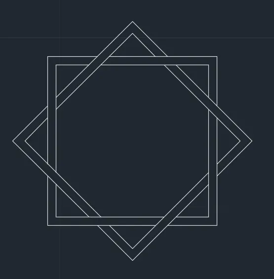
Figure - 11
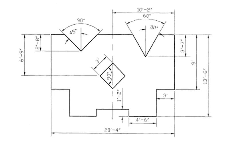
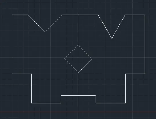
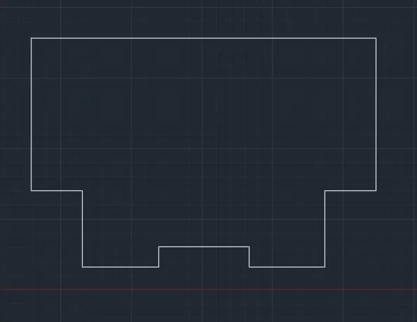
- Draw a line of 9' downwards, and the a line of 3' towards right.
- Then a line of 4'6" downwards and then again line of 4'6" right.
- From there, a line of 1'2" upwards and 5'4" rightwards and again 1'2" downwards.
- Then a line of 4'6" rightwards and 4'6" upwards.
- Then a line of 3' towards right and then a line of 9' towards up.
- Click on Close.
- Draw a square of side 3' and then rotate it by 45 degrees.
- From a distance of 10'2" from x-axis towards right and 6'9" from the y- axis towards down, move the rotated square by selecting the gc as base point.
- On the top line, at 5'1" from both sides, draw a line downwards of length 2'8" on left and 3'7" on right.
- From the end of the left line, draw lines at 45 degrees on both sides to intersect it with the above line.
- From the end of the right line, draw lines at 60 degrees on both sides to intersect it with the above line.
- Trim off the excess lines from the figure.
RESULT:
The figure is drawn and is shown below