Creating a Residence Layout, Seating plan, Toilet and Utility room plan using AutoCad
AIM:
The aim is to create a Residence Layout, Seating plan, Toilet and Utility room plan using AutoCad, mark the dimensions provided, and use layers.
INTRODUCTION:
Layers - Layers are used for organising objects in a drawing. They are used to reduce the complexity seen in the drawing by arranging in different layers and to improve the experience by hiding the information that is not needed at the moment.
There are many functions provided with the layer option such as locking layers, layer visibility, layer filters, overriding layers, etc.
Fillet - It is a tool used in AutoCAD to create a rounded edge between two lines that may or may not be intersecting. It can be selected from the modify ribbon or by typing fillet on the command bar.
Trim - It is a tool used in AutoCAD to remove the excess lines or parts of object without entirely removing the object or the line. It is one of the most commonly used tools in AutoCAD.
PROCEDURE:
Figure - 1
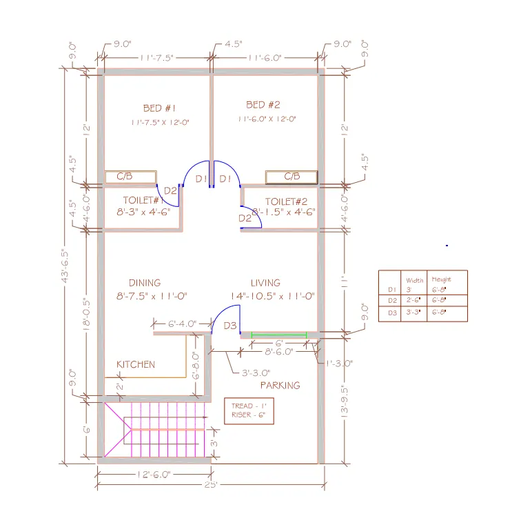
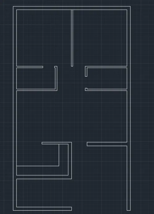
- Using the xline command, construction lines are drawn and then lines are used to draw the house plan.
- The plan was started from the lower left corner and then the kitchen and dining room were drafted using the dimensions provided.
- After that, bedroom #1 and toilet #1 were drafted using the commands by entering the provided dimensions.
- After that, bedroom #2 and toilet #2 were drafted using the commands by entering the provided dimensions.
- Later, the living room was drafted in the given dimension.
- Then the parking space is also drafted.
- Offset command is commonly used to give the wall thickness. Offset of 300mm is given in exterior walls and 150mm is given in interior walls.
- The excess lines that are not needed or may be extending after intersecting were trimmed using trim command.
- The corners of the lines in rooms were joined by using fillet command. The fillet radius was set to 0 before filleting these.
- The dimension for these rooms were checked and corrected if needed by entering dim command.
- Following the completion of walls, doors were drawn on the entrances of the provided size and direction of swing.
- Then later, the window was also provided in the given dimension and on the right place.
- After drafting doors and windows, the dimensions were marked on the drawings as mentioned in the question.
- Later the text was entered on the drawings on the needed place such as mentioning of the room size and door sizes, etc.
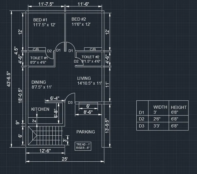
- Once all the drawings were completed, layers were created according to the drawing such as doors, windows, walls exterior, walls interior, text, dimensions, stairs, etc,
- Then the corresponding objects were selected and placed on the respective layers accordingly.
- The layers were given separate colours to distinguish them from each other.
RESULT:
The figure is drafted and objects were placed in respective layers and are shown below.
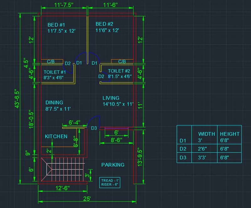
Figure - 2
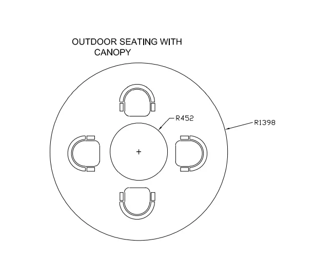
- A circle of radius 1398mm is drawn. Then again another circle of radius 452 with same centre as that of the previous circle.
- Then after that the canopy is drawn with assumed dimensions.
- Then the dimensions were marked on the drawing using dim command.
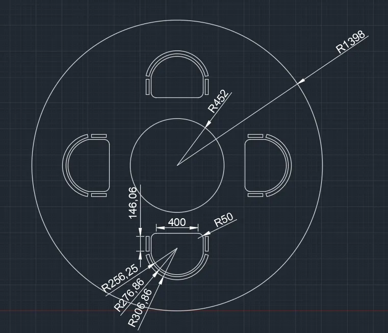
- After the dimensions are marked, the layers are created according to the drawing.
- Then the corresponding objects were selected and placed on the respective layers accordingly.
- The layers were given separate colours to distinguish them from each other.
RESULT:
The figure is drafted and objects were placed in respective layers and are shown below.
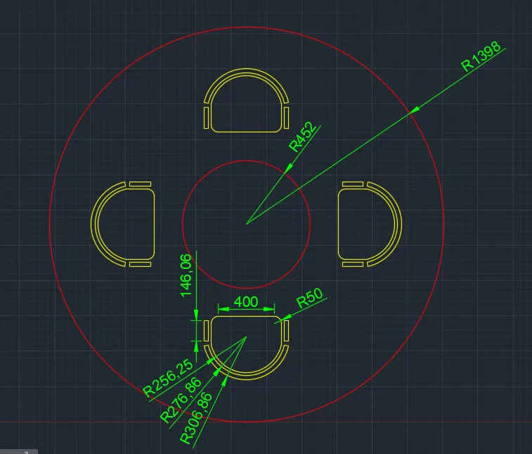
Figure - 3
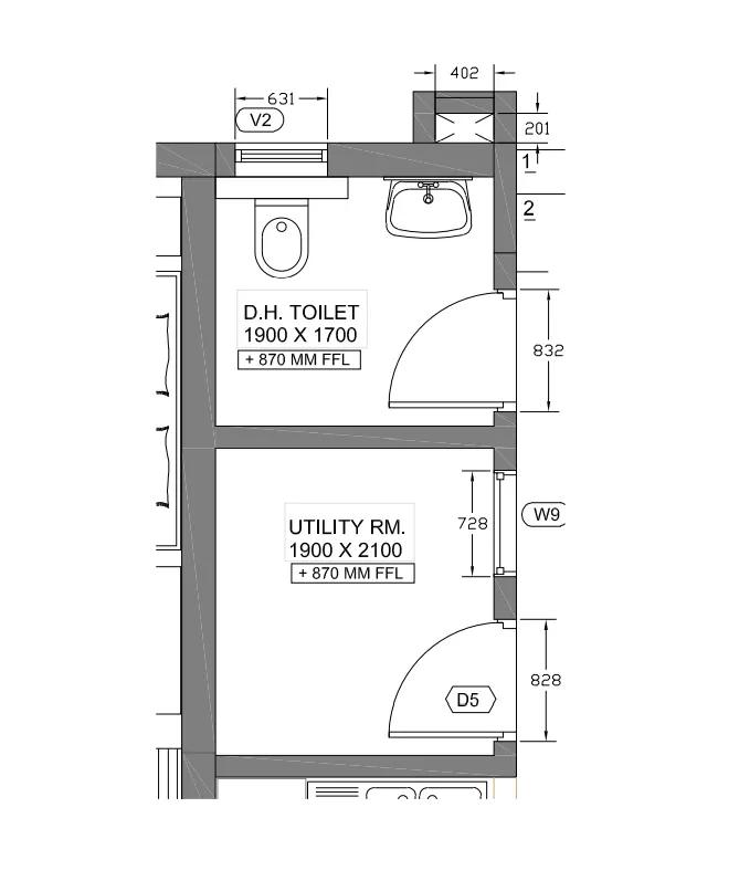
- Using the xline command, construction lines are drawn and then lines are used to draw the house plan.
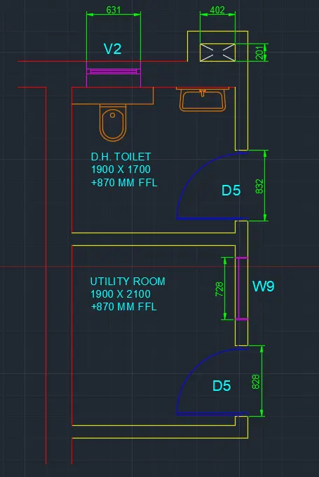
- The plan was started from the lower left corner and then the utility room walls were was first drafted.
- After that the Toilet walls were drafted.
- Following the completion of the walls, the w/c and sink were drafted.
- Offset command is commonly used to give the wall thickness. Offset of 300mm is given in exterior walls and 150mm is given in interior walls.
- The excess lines that are not needed or may be extending after intersecting were trimmed using trim command.
- The corners of the lines in rooms were joined by using fillet command. The fillet radius was set to 0 before filleting these.
- The dimension for these rooms were checked and corrected if needed by entering dim command.
- Then doors were drawn on the entrances of the provided size and direction of swing.
- Then later, the window and ventilation were also provided in the given dimensions and on the right places.
- After drafting doors and windows, the dimensions were marked on the drawings as mentioned in the question.
- Later the text was entered on the drawings on the needed place such as mentioning of the room size and door sizes, etc.
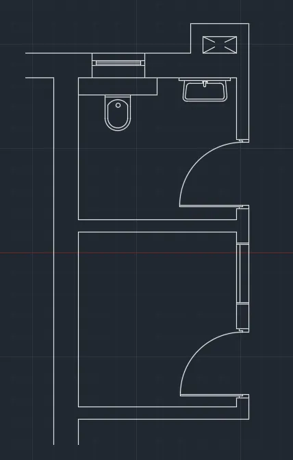
- Once all the drawings were completed, layers were created according to the drawing such as doors, windows, walls exterior, walls interior, text, dimensions, etc,
- Then the corresponding objects were selected and placed on the respective layers accordingly.
- The layers were given separate colours to distinguish them from each other.
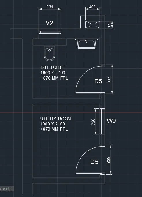
RESULT:
The figure is drafted and objects were placed in respective layers and are shown below.