Creation of geometries by Coordinate system methods using AutoCad
AIM:
The aim is to create geometries by coordinate system methods using AUTOCAD with the commands like line and circle drawing tools.
The geometries P-1 and P-2 are drawn using all the coordinate systems, and other remaining geometries are drawn using any of the coordinate systems.
INTRODUCTION:
Coordinate systems:
It is a system where numbers are used to determine the unique position of points and/or other geometric elements.
The various coordinate systems are:
- Absolute Coordination System: In this system, all points are established at some distance in the x & y axes from the origin (0,0).
- Relative Coordinate System: In this system, the first point is established from the origin (0,0) and the previous point is taken as reference from the second point.
- Direct Distance entry method: In this system, the user has to point the cursor in the desired direction and enter the required distance or length.
The relative coordinate system is further classified into -
- Relative rectangular coordinates: Here, the points after the first point are typed as '@x,y'.
- Relative polar coordinate: Here, distance and the angle from the previous point is given to get the next point. The points are entered as '@distance<angle'
PROCEDURE:
Starting AutoCAD
- Opening AutoCAD:
- Click on the AutoCAD application.
- Click on start drawing.
- In the command line, type 'STARTUP'
- Type new value of startup - 1.
- In the 'create new drawing' dialog box, we select the imperial system.
- Set the limits by entering 0,0 in the lower left corner and 100,100 in the top right corner.
This procedure is followed for each new drawing.
⋆Drafting the geometry given in P-1
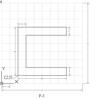
a) Using Absolute coordinate system:
- Select the line tool by entering the line command in the command tab.
- Specify the starting coordinate of point 1 as 2,1 in the command line.
- Specify the next coordinate of point 2 as 2,7 in the command line.
- Specify the next coordinate of point 3 as 8,7 in the command line.
- Specify the next coordinate of point 4 as 8,6 in the command line.
- Specify the next coordinate of point 5 as 3,6 in the command line.
- Specify the next coordinate of point 6 as 3,2 in the command line.
- Specify the next coordinate of point 7 as 8,2 in the command line.
- Specify the next coordinate of point 8 as 8,1 in the command line.
- Click close on the command line.
RESULT:

b) Using Relative rectangular coordinate system:
- Select the line tool by entering the line command in the command tab.
- Specify the starting coordinate of point 1 as 2,1 in the command line.
- Specify the next coordinate of point 2 as @0,6 in the command line.
- Specify the next coordinate of point 3 as @6,0 in the command line.
- Specify the next coordinate of point 4 as @0,-1 in the command line.
- Specify the next coordinate of point 5 as @-5,0 in the command line.
- Specify the next coordinate of point 6 as @0,-4 in the command line.
- Specify the next coordinate of point 7 as @5,0 in the command line.
- Specify the next coordinate of point 8 as @0,-1 in the command line.
- Click close on the command line.
Result
c) Using Relative Polar coordinate system:
- Select the line tool by entering the line command in the command tab.
- Specify the starting coordinate of point 1 as 2,1 in the command line.
- Specify the next coordinate of point 2 as @6<90 in the command line.
- Specify the next coordinate of point 3 as @6<0 in the command line.
- Specify the next coordinate of point 4 as @1<270 in the command line.
- Specify the next coordinate of point 5 as @5<180 in the command line.
- Specify the next coordinate of point 6 as @4<270 in the command line.
- Specify the next coordinate of point 7 as @5<0 in the command line.
- Specify the next coordinate of point 8 as @1<270 in the command line.
- Click close on the command line.
RESULT:
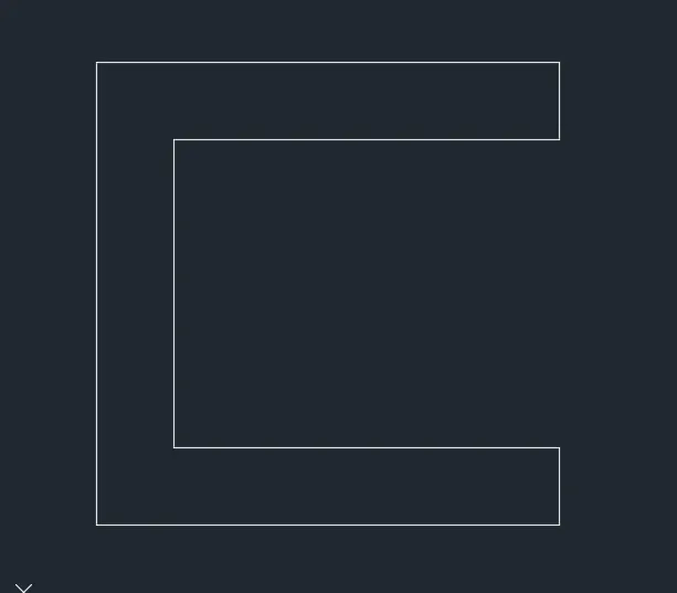
d)Direct distance entry method:
- Select the line tool by entering the line command in the command tab.
- Specify the starting coordinate of point 1 as 2,1 in the command line.
- Place the cursor above point 1 and enter 6.
- Place the cursor right of point 2 and enter 6.
- Place the cursor below point 3 and enter 1.
- Place the cursor left of point 4 and enter 5.
- Place the cursor below point 5 and enter 4.
- Place the cursor right of point 6 and enter 5.
- Place the cursor below point 7 and enter 1.
- Click close on the command line.
RESULT:
⋆Drafting the geometry given in P-2
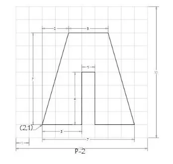
a) Using Absolute coordinate system:
- Select the line tool by entering the line command in the command tab.
- Specify the starting coordinate of point 1 as 2,1 in the command line.
- Specify the next coordinate of point 2 as 4,8 in the command line.
- Specify the next coordinate of point 3 as 7,8 in the command line.
- Specify the next coordinate of point 4 as 9,1 in the command line.
- Specify the next coordinate of point 5 as 6,1 in the command line.
- Specify the next coordinate of point 6 as 6,5 in the command line.
- Specify the next coordinate of point 7 as 5,5 in the command line.
- Specify the next coordinate of point 8 as 5,1 in the command line.
- Click close on the command line.
RESULT:
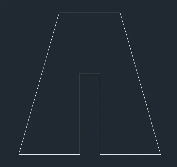
b) Using Relative rectangular coordinate system:
- Select the line tool by entering the line command in the command tab.
- Specify the starting coordinate of point 1 as 2,1 in the command line.
- Specify the next coordinate of point 2 as @2,7 in the command line.
- Specify the next coordinate of point 3 as @3,0 in the command line.
- Specify the next coordinate of point 4 as @2,-7 in the command line.
- Specify the next coordinate of point 5 as @-3,0 in the command line.
- Specify the next coordinate of point 6 as @0,4 in the command line.
- Specify the next coordinate of point 7 as @-1,0 in the command line.
- Specify the next coordinate of point 8 as @0,-4 in the command line.
- Click close on the command line.
RESULT:
c) Using Relative Polar coordinate system:
- Select the line tool by entering the line command in the command tab.
- Specify the starting coordinate of point 1 as 2,1 in the command line.
- Specify the next coordinate of point 2 as @7.28<74 in the command line.
- Specify the next coordinate of point 3 as @3<0 in the command line.
- Specify the next coordinate of point 4 as @7.28<286 in the command line.
- Specify the next coordinate of point 5 as @3<180 in the command line.
- Specify the next coordinate of point 6 as @4<90 in the command line.
- Specify the next coordinate of point 7 as @1<180 in the command line.
- Specify the next coordinate of point 8 as @4<270 in the command line.
- Click close on the command line.
RESULT:
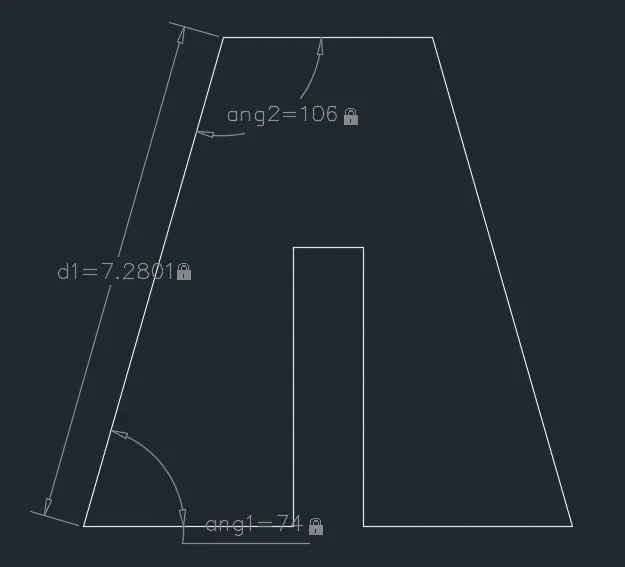
d)Direct distance entry method:
- Select the line tool by entering the line command in the command tab.
- Specify the starting coordinate of point 1 as 2,1 in the command line.
- Place the cursor at angle 74 from point 1 and enter 7.28.
- Place the cursor right of point 2 and enter 3.
- Place the cursor at angle 286 from point 3 and enter 7.28.
- Place the cursor left of point 4 and enter 3.
- Place the cursor above point 5 and enter 4.
- Place the cursor left of point 6 and enter 1.
- Place the cursor below point 7 and enter 4.
- Click close on the command line.
RESULT:
⋆Drafting the geometry given in P-4
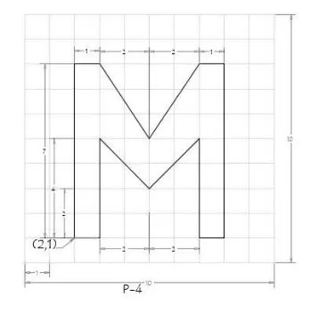
Using Relative coordinate system:
- Select the line tool by entering the line command in the command tab.
- Specify the starting coordinate of point 1 as 2,1 in the command line.
- Specify the next coordinate of point 2 as @0,7 in the command line.
- Specify the next coordinate of point 3 as @1,0 in the command line.
- Specify the next coordinate of point 4 as @2,-3 in the command line.
- Specify the next coordinate of point 5 as @2,3 in the command line.
- Specify the next coordinate of point 6 as @1,0 in the command line.
- Specify the next coordinate of point 7 as @0,-7 in the command line.
- Specify the next coordinate of point 8 as @-1,0 in the command line.
- Specify the next coordinate of point 9 as @0,4 in the command line.
- Specify the next coordinate of point 10 as @-2,-2 in the command line.
- Specify the next coordinate of point 11 as @-2,2 in the command line.
- Specify the next coordinate of point 12 as @0,-4 in the command line.
- Click close on the command line.
RESULT:

⋆Drafting the geometry given in P-5
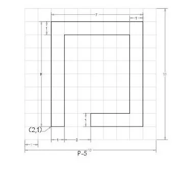
Using Relative coordinate system:
- Select the line tool by entering the line command in the command tab.
- Specify the starting coordinate of point 1 as 2,1 in the command line.
- Specify the next coordinate of point 2 as @0,8 in the command line.
- Specify the next coordinate of point 3 as @7,0 in the command line.
- Specify the next coordinate of point 4 as @0,-8 in the command line.
- Specify the next coordinate of point 5 as @-4,0 in the command line.
- Specify the next coordinate of point 6 as @0,1 in the command line.
- Specify the next coordinate of point 7 as @3,0 in the command line.
- Specify the next coordinate of point 8 as @0,6 in the command line.
- Specify the next coordinate of point 9 as @-5,0 in the command line.
- Specify the next coordinate of point 10 as @0,-7 in the command line.
- Click close on the command line.
RESULT:
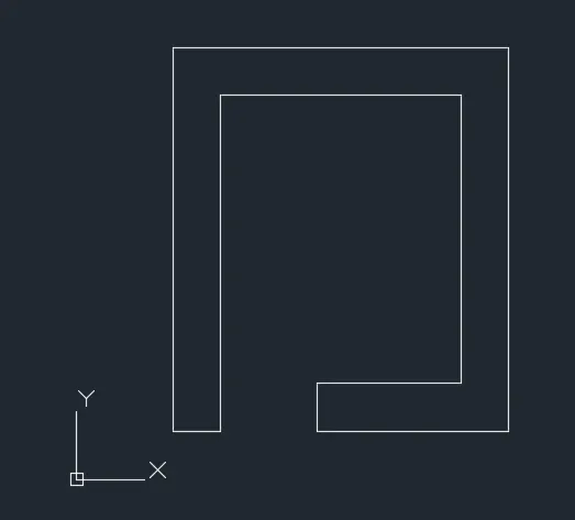
⋆Drafting the geometry given in P-7
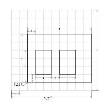
Using Relative coordinate system:
- Select the line tool by entering the line command in the command tab.
- Specify the starting coordinate of point 1 as 2,1 in the command line.
- Specify the next coordinate of point 2 as @0,6 in the command line.
- Specify the next coordinate of point 3 as @8,0 in the command line.
- Specify the next coordinate of point 4 as @0,-6 in the command line.
- Click close on the command line.
- Select the line tool by entering the line command in the command tab.
- Specify the starting coordinate of point 1 as 3,2 in the command line.
- Specify the next coordinate of point 2 as @0,3 in the command line.
- Specify the next coordinate of point 3 as @2,0 in the command line.
- Specify the next coordinate of point 4 as @0,-3 in the command line.
- Click close on the command line.
- Select the line tool by entering the line command in the command tab.
- Specify the starting coordinate of point 1 as 6,2 in the command line.
- Specify the next coordinate of point 2 as @0,3 in the command line.
- Specify the next coordinate of point 3 as @2,0 in the command line.
- Specify the next coordinate of point 4 as @0,-3 in the command line.
- Click close on the command line.
RESULT:
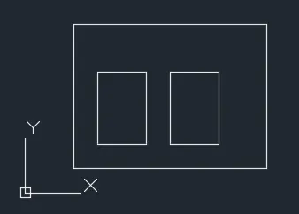
⋆Drafting the geometry given in P-8
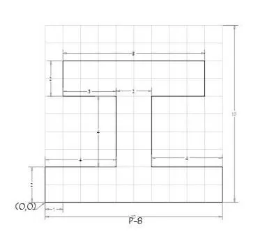
Using Relative coordinate system:
- Select the line tool by entering the line command in the command tab.
- Specify the starting coordinate of point 1 as 0,0 in the command line.
- Specify the next coordinate of point 2 as @0,2 in the command line.
- Specify the next coordinate of point 3 as @4,0 in the command line.
- Specify the next coordinate of point 4 as @0,4 in the command line.
- Specify the next coordinate of point 5 as @-3,0 in the command line.
- Specify the next coordinate of point 6 as @0,2 in the command line.
- Specify the next coordinate of point 7 as @8,0 in the command line.
- Specify the next coordinate of point 8 as @0,-2 in the command line.
- Specify the next coordinate of point 9 as @-3,0 in the command line.
- Specify the next coordinate of point 10 as @0,-4 in the command line.
- Specify the next coordinate of point 11 as @4,0 in the command line.
- Specify the next coordinate of point 12 as @0,-2 in the command line.
- Click close on the command line.
RESULT:
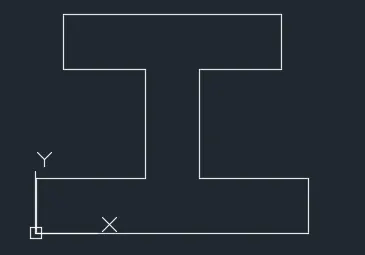
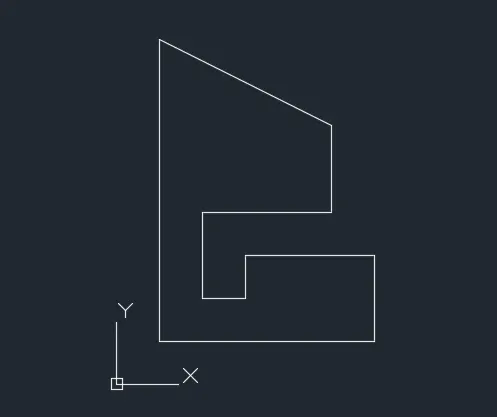
⋆Drafting the geometry given in P-9
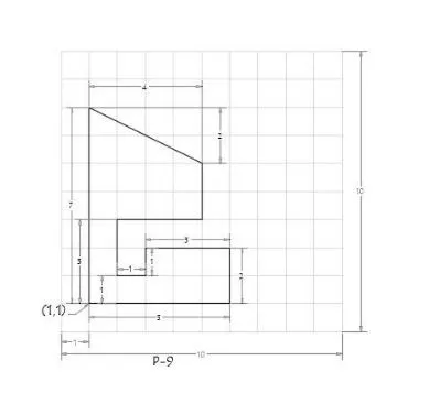
Using Relative coordinate system:
- Select the line tool by entering the line command in the command tab.
- Specify the starting coordinate of point 1 as 1,1 in the command line.
- Specify the next coordinate of point 2 as @0,7 in the command line.
- Specify the next coordinate of point 3 as @4,-2 in the command line.
- Specify the next coordinate of point 4 as @0,-2 in the command line.
- Specify the next coordinate of point 5 as @-3,0 in the command line.
- Specify the next coordinate of point 6 as @0,-2 in the command line.
- Specify the next coordinate of point 7 as @1,0 in the command line.
- Specify the next coordinate of point 8 as @0,1 in the command line.
- Specify the next coordinate of point 9 as @3,0 in the command line.
- Specify the next coordinate of point 10 as @0,-2 in the command line.
- Click close on the command line.
RESULT:
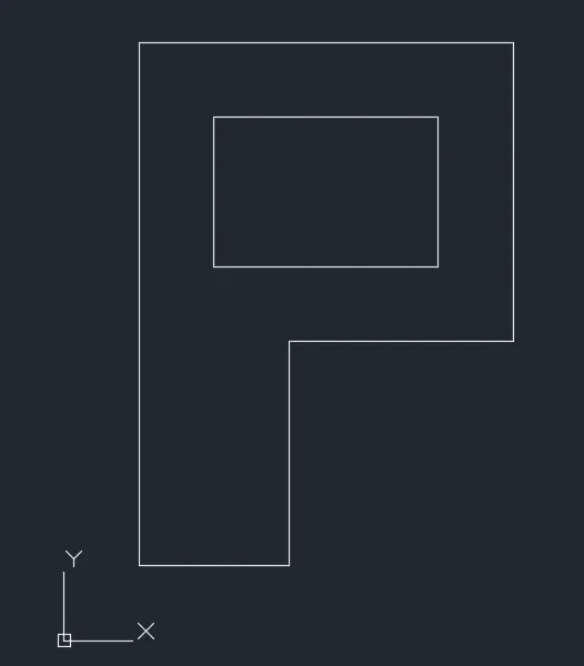
⋆Drafting the geometry given in P-10
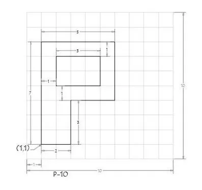
Using Relative coordinate system:
- Select the line tool by entering the line command in the command tab.
- Specify the starting coordinate of point 1 as 1,1 in the command line.
- Specify the next coordinate of point 2 as @0,7 in the command line.
- Specify the next coordinate of point 3 as @5,0 in the command line.
- Specify the next coordinate of point 4 as @0,-4 in the command line.
- Specify the next coordinate of point 5 as @-3,0 in the command line.
- Specify the next coordinate of point 6 as @0,-3 in the command line.
- Click close on the command line.
- Select the line tool by entering the line command in the command tab.
- Specify the starting coordinate of point 1 as 2,5 in the command line.
- Specify the next coordinate of point 2 as @0,2 in the command line.
- Specify the next coordinate of point 3 as @3,0 in the command line.
- Specify the next coordinate of point 4 as @0,-2 in the command line.
- Click close on the command line.
RESULT:
⋆Drafting the geometry given in Profile wood
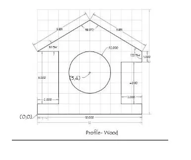
Using Relative coordinate system:
- Select the line tool by entering the line command in the command tab.
- Specify the starting coordinate of point 1 as 0,0 in the command line.
- Specify the next coordinate of point 2 as @0,1 in the command line.
- Specify the next coordinate of point 3 as @2,0 in the command line.
- Specify the next coordinate of point 4 as @0,5 in the command line.
- Specify the next coordinate of point 5 as @-2,0 in the command line.
- Specify the next coordinate of point 6 as @5,3 in the command line.
- Specify the next coordinate of point 7 as @5,-3 in the command line.
- Specify the next coordinate of point 8 as @0,-1 in the command line.
- Specify the next coordinate of point 9 as @-2,0 in the command line.
- Specify the next coordinate of point 10 as @0,-4 in the command line.
- Specify the next coordinate of point 11 as @2,0 in the command line.
- Specify the next coordinate of point 12 as @0,-1 in the command line.
- Click close on the command line.
- Select the circle tool by entering the circle command in the command tab.
- Specify 5,4 as the center point of the circle.
- Specify 2 as the radius of the circle.
RESULT:
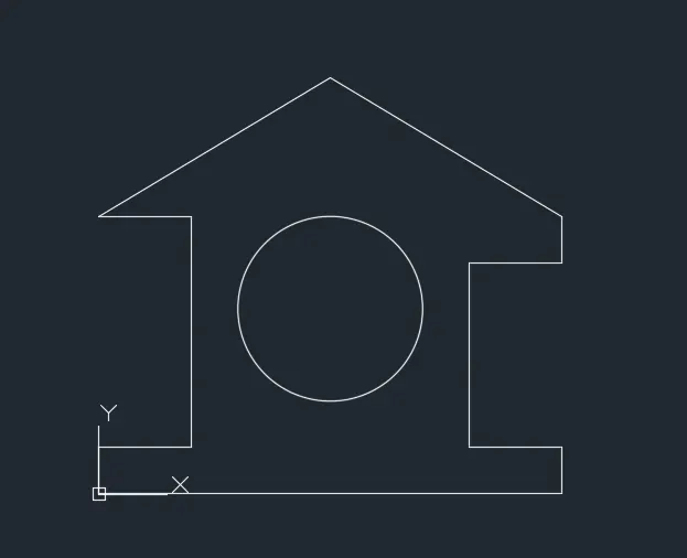
⋆Drafting the geometry given in Queen post truss
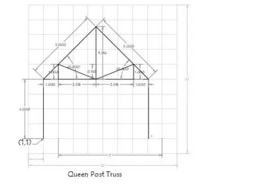
- Select the line tool by entering the line command in the command tab.
- Specify the starting coordinate of point 1 as 1,1 in the command line.
- Specify the next coordinate of point 2 as @0,4 in the command line.
- Specify the next coordinate of point 3 as @5<45 in the command line.
- Specify the next coordinate of point 4 as @5<315 in the command line.
- Specify the next coordinate of point 5 as @0,-4 in the command line. Press Enter.
- Select the line tool by entering the line command in the command tab.
- Place the starting point of line in point 2.
- Specify the next coordinate of point 6 as @1,0 in the command line.
- Specify the next coordinate of point 7 as @0,1 in the command line. Press Enter
- Select the line tool by entering the line command in the command tab.
- Place the starting point of line in point 4.
- Specify the next coordinate of point 8 as @-1,0 in the command line.
- Specify the next coordinate of point 9 as @0,1 in the command line. Press Enter
- Select the line tool by entering the line command in the command tab.
- Place the starting point of line in point 6 and ending point in point 8. Press Enter.
- Select the line tool by entering the line command in the command tab.
- Place the starting point of line in point 3 and ending point as 0,-3.536. This is point 10
- Draw line from the current point 10 to point 7.
- Then draw a line from point 10 to point 9
RESULT:
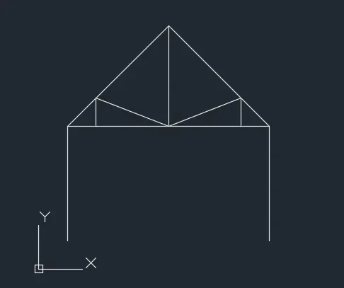
⋆Drafting the geometry given in Mono pitch
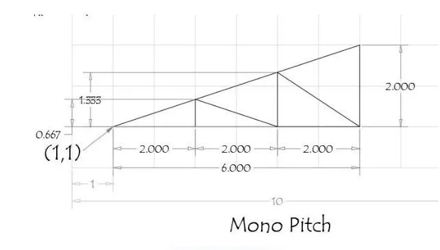
- Select the line tool by entering the line command in the command tab.
- Specify the starting coordinate of point 1 as 1,1 in the command line.
- Specify the next coordinate of point 2 as @6,0 in the command line.
- Specify the next coordinate of point 3 as @0,2 in the command line.
- Specify the next coordinate of point 4 as @0,5 in the command line.
- Specify the next coordinate of point 5 as 1,1 in the command line. Click Enter.
- Select the line tool by entering the line command in the command tab.
- Specify the starting coordinate of point 6 as 3,1 in the command line.
- Specify the next coordinate of point 7 as @0,0.667 in the command line.
- Specify the next coordinate of point 8 as 5,1 in the command line.
- Specify the next coordinate of point 9 as @0,1.333 in the command line.
- Specify the next coordinate of point 10 as @7,1 in the command line.
- Click close on the command line.
RESULT:
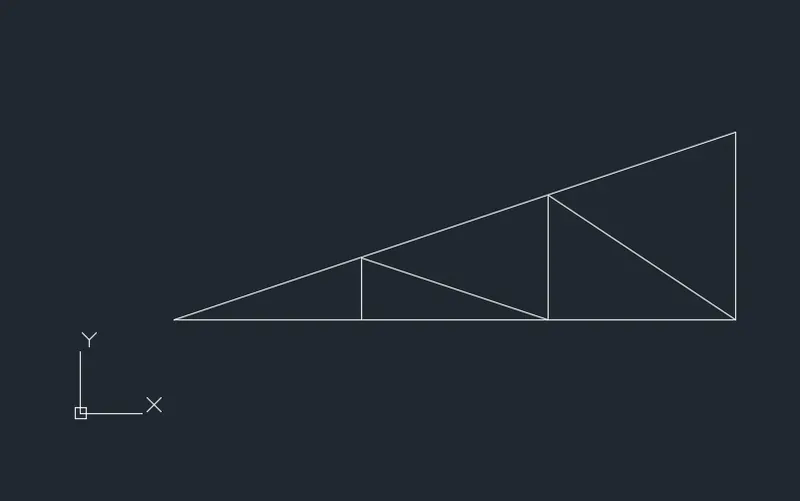
RESULT:
Thus the provided drawings are drafted using AutoCAD and the procedure is explained.