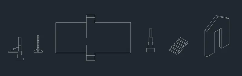
Creating a Floor plan, Footing detail and Isometric view using AutoCad
AIM:
The aim is to create a floor plan, footing details and isometric view using AutoCAD.
INTRODUCTION:
Isometric view:
It is used to project 3D objects in a 2D plane. It shows what a 3D object will look like in a 2D view. It is also called Isometric projection. It is not a 3D model.
In Isometric drafting, there are three different options in which you can draw they are, isoplane left, isoplane right and isoplane top.
Copy - It is a modification tool used in AutoCAD that is used to copy a single object into more number of objects. For doing this, first, the object has to be selected. Then the base point has to be selected. After that, the new location has to be selected in which the object has to be copied.
Move - It is a modification tool used in AutoCAD that is used to move an object from the current location to another location. For doing this, first, the object has to be selected. Then the base point has to be selected. After that, the new location has to be selected in which the object has to be moved.
Offset - It is a modification tool used in AutoCAD that is used to create multiple objects inwards or outwards of the current object or from a equal distance from the original position.
PROCEDURE:
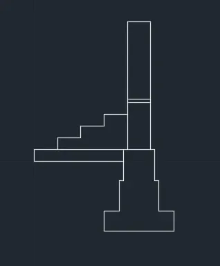
⋆Drafting the figure given in C-1
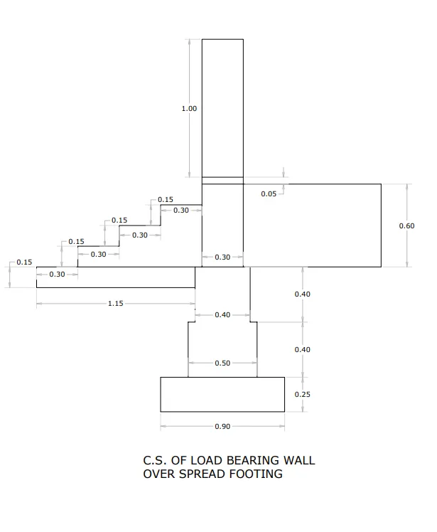
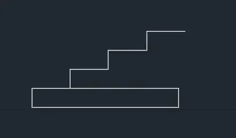
- Use the line command and draw a box of 1.15 x 0.15.
- From 0.3 distance from the top left, draw a line of 0.15 upwards and 0.3 rightwards. Repeat this 2 more times.
- Draw 0.45 downwards from this point.
- From the top right of first box, draw line 0.3 rightwards and 0.4 downwards.
- Then 0.05 rightwards and 0.4 downwards.
- Then 0.2 rightwards and 0.25 downwards and 0.9 leftwards.
- Then 0.25 upwards and 0.2 rightwards.
- Then 0.4 upwards and 0.05 rightwards and then 0.4 upwards
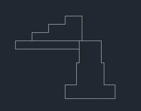
- From 0.05 left of the top right corner of the third box, draw 0.6 upwards and 0.3 leftwards and 0.15 downwards.
- Draw a rectangle above this of size 0.3 x 0.05.
- Draw another rectangle above this of size 0.3 x 1
RESULT:
The figure is drawn and is shown below
⋆Drafting the figure given in C-2
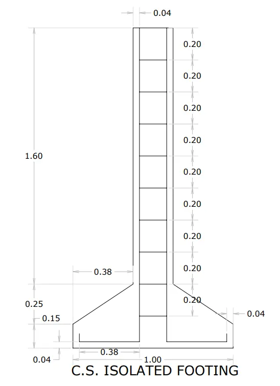
- Select line tool and draw a line of length 1 rightwards.
- Draw line of length 0.15 upwards on both ends of the previous line.
- From the left end, draw line by entering @0.38,0.25 and from right end enter @-0.38,0.25
- Now draw a line of length 1.6 upwards on either side and use the copy tool to copy this line to other side.
- From the top of the new line, draw two lines of length 0.04 each towards the other line.
- Then draw line of length 1.96 downwards on both sides.
- Now draw line of length 0.38 leftwards from the left centre line, and towards right from the right centre line.
- Draw a line of length 0.04 upwards on both sides.
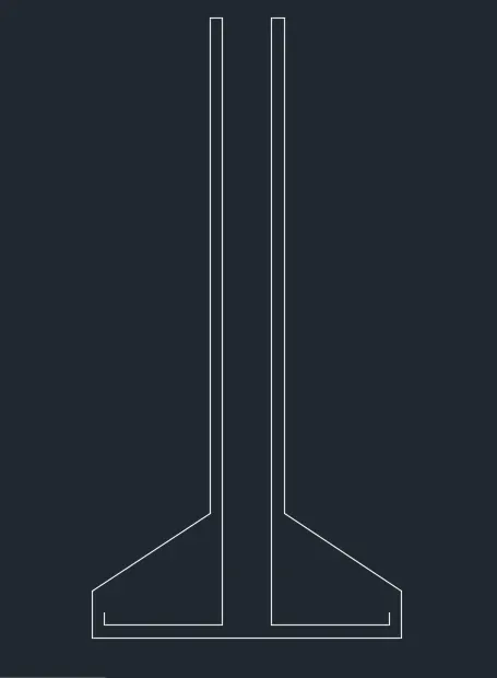
- Draw a line connecting the two long lines at the top.
- Select offset tool and enter distance as 0.2.
- Now select the horizontal line at the top and select multiple option.
- place the next offset below the previous line and make 9 other lines.
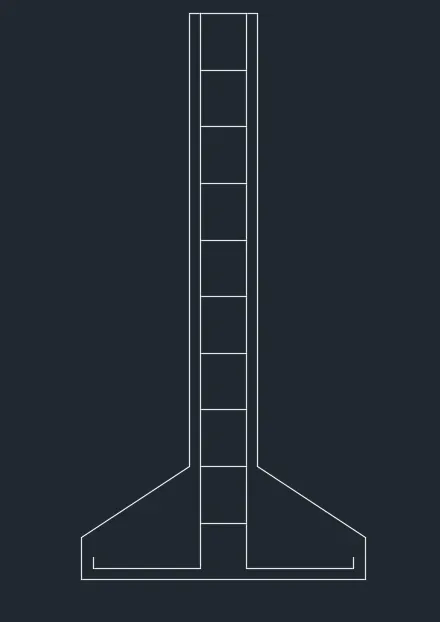
RESULT:
The figure is drawn and is shown below,
⋆Drafting the figure given in C-3
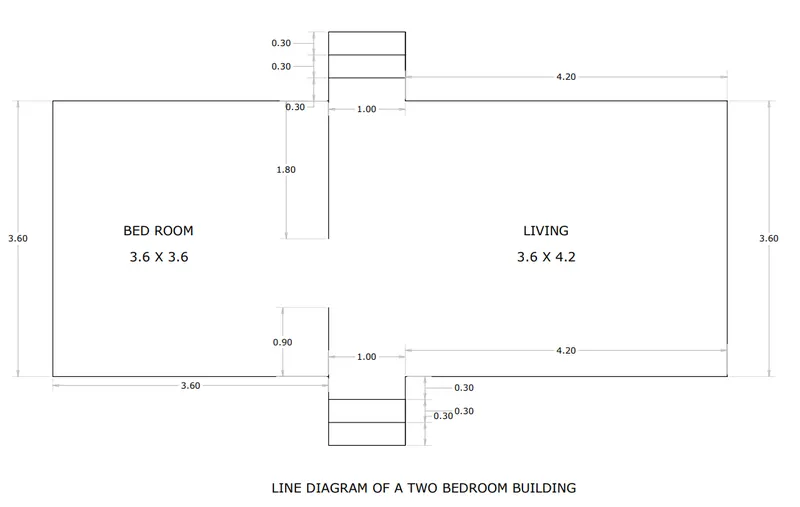
- Draw a line of length 3.6 horizontally. From the left end draw another line of length 3.6 upwards and from the right end, draw a line of length 0.9 upwards.
- From top left corner draw a line of length 3.6 rightwards and then draw a line of length 1.8 downwards.
- Now from the top right corner draw a line of length 0.9 upwards and then another line of length 1 rightwards.
- Then copy the line of length 0.9 to the right end of line of length 1.
- Now from the bottom right corner, draw a line of length 0.9 downwards and then another line of length 1 rightwards.
- Then copy the line of length 0.9 to the right end of line of length 1.
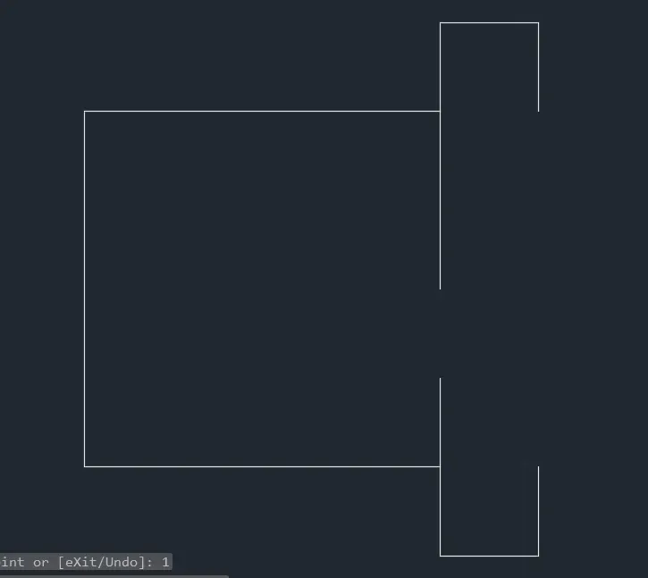
- Now offset the line of length 1 below it twice on the top side, and offset it above the line in bottom side.
- From the top right end, draw a line of length 4.2 rightwards. From there draw a line of length 3.6 downwards.
- Draw a line of length 4.2 leftwards.
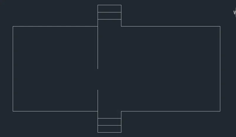
RESULT:
The figure is drawn and is shown below,
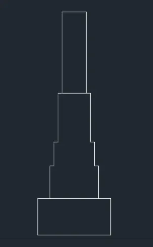
⋆Drafting the figure given in C-4
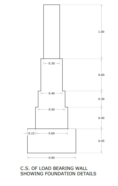
- Draw a line of length 0.9 and then draw lines of length 0.45 upwards from both ends of first line.
- Draw a line connecting these two lines of length 0.9
- From 0.15 right from the top left corner, draw a line of length 0.4 upwards and another line of length 0.05 rightwards.
- Draw a line of length 0.3 upwards from the last point and then a line of length 0.05 rightwards.
- Then draw a line of length 0.6 upwards from the last point and then a line of length 0.4 rightwards.
- Draw a line of length 0.6 downwards from the last point and then a line of length 0.05 rightwards.
- Then draw a line of length 0.3 downwards from the last point and then a line of length 0.05 rightwards.
- Draw a line of length 0.4 downwards from the last point.
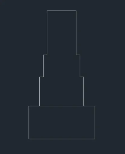
- From 0.05 right from the top left corner, draw a line of length 1 upwards and another line of length 0.3 rightwards.
- Draw a line of length 1 downwards from the last point.
RESULT:
The figure is drawn and is shown below,
⋆Drafting the figure given in C-5
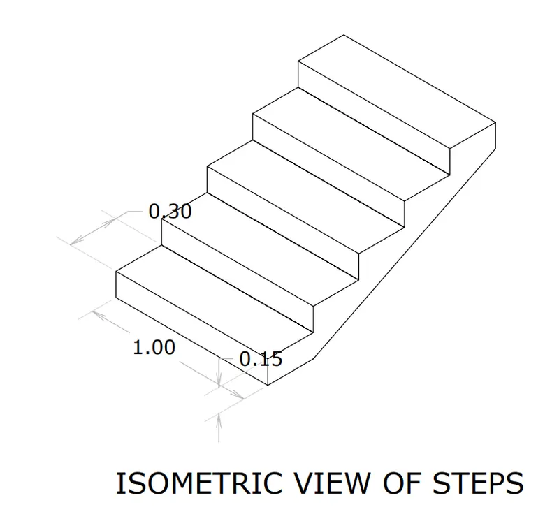
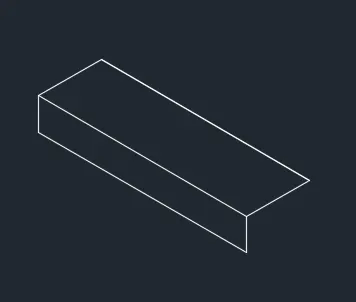
- Turn on the isometric drafting to draw object in isometric view.
- Keep in Isoplane Left by pressing F5 key and draw a line of length 1 in left plane.
- Draw a line upwards of length 0.15 in both ends of the previous line.
- Join the two lines by a line of length 1
- Change to Isoplane top by pressing F5 and draw a line in right direction of length 0.3 from both ends of the box
- Join the two lines by a line of length 1
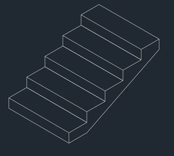
Copy entire drawing and select left bottom corner as base point and paste the copy 4 times over the existing drawing to create the steps
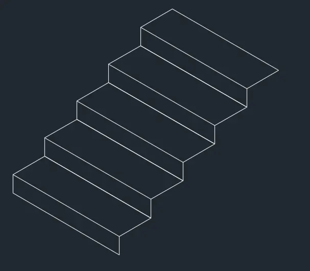
- Draw a line from the lower right corner in right direction of length 0.3
- Draw a line of length 0.15 from the top right corner downwards.
- Join these two lines by another line.
RESULT:
The figure is drawn and is shown below,
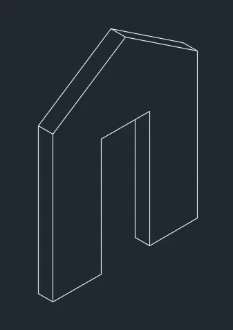
⋆Drafting the figure given in C-6
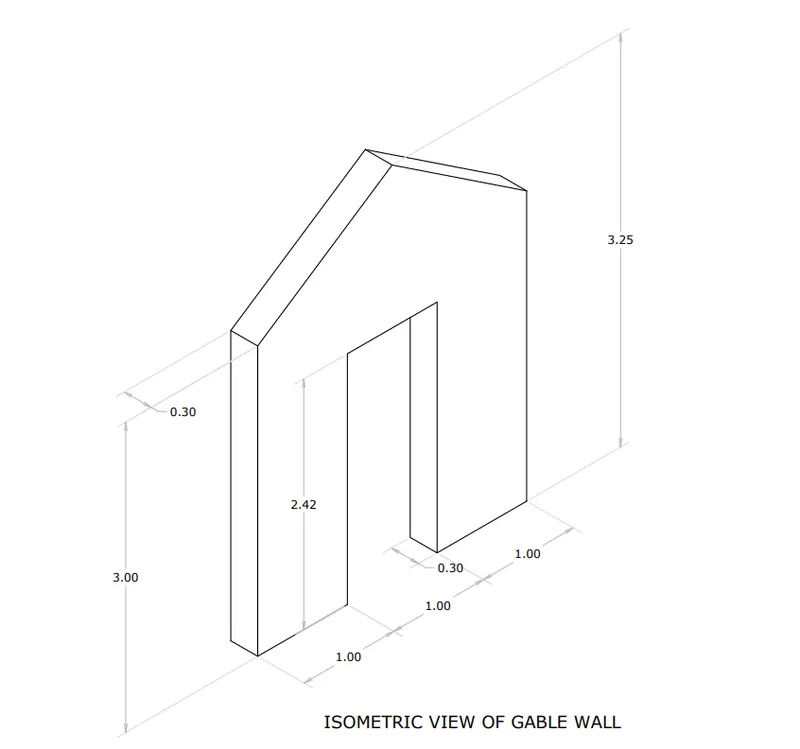
- Turn on the isometric drafting to draw object in isometric view.
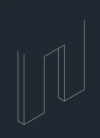
- Keep in Isoplane Right by pressing F5 key and draw a line of length 1 in right plane.
- Draw a line of length 1 from left end upwards.
- From the left end of the bottom line draw a line of length 0.3 in left direction and then another line of length 3 in upwards.
- Draw a line of length 2.42 from the right end, then another line of length 1 rightwards.
- Then a line of 2.42 length downwards, and a line of 0.3 towards left and from there, draw a line upwards to meet at the line present there.
- From the bottom right corner, draw a line of length 1 towards right and then draw it upwards in length 3.
- From the left upper corner, join the two ends on the lines.
- Then draw a line towards the midpoint of the right side wall at a height of 4 from the ground.
- Copy this to the nearby wall also and join the other end.
- Draw line towards the right top corner also and another line from there towards left of length 0.3
- Join it to the center top line.
RESULT:
The figure is drawn and is shown below,
RESULT:
The figures provided are drafted using AutoCAD by using tools like copy, move in both 2D topview and also in isometric view. The drafted drawing is provided below,