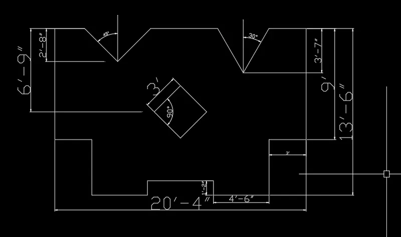
Drafting of various geometries using Chamfer, Fillet tool in AutoCad
Aim: Week 3 Challange "Drafting of various geometries using Chamfer, Fillet tool in AutoCad".
Solution P-1,
Starting the autocad. There are two ways:-
a.)By setting a page with custom settings.(start from scratch)
b.)By choosing premade template.
adopting a.)
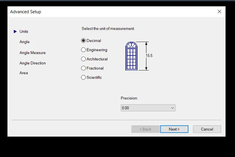
After opening autocad type "units" command to set units.
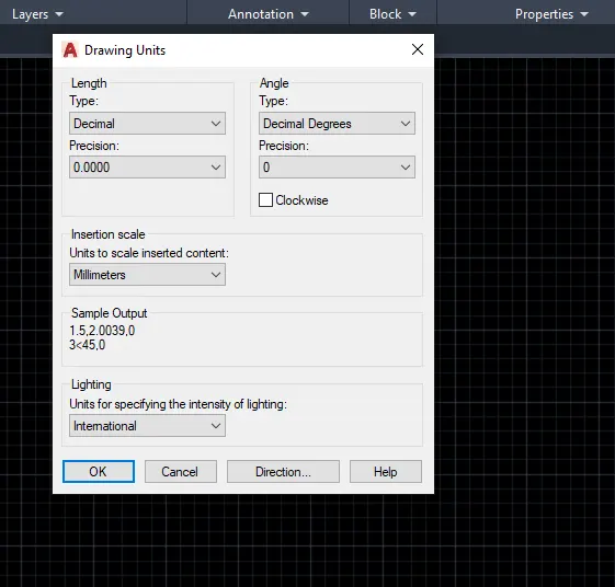
click ok.
Checking by making a line of 3.00.
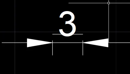
Above image tells us that arrow size, text size are very large.
Press "D" Enter. To change dimension settings.
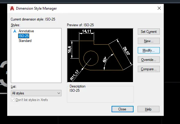
Click modify.
Settting 1.)
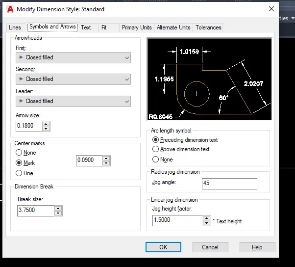
Setting 2.)
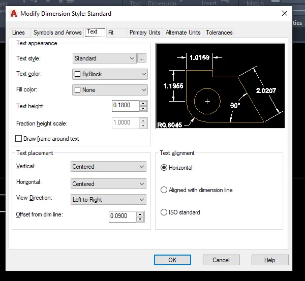
Setting 3.)
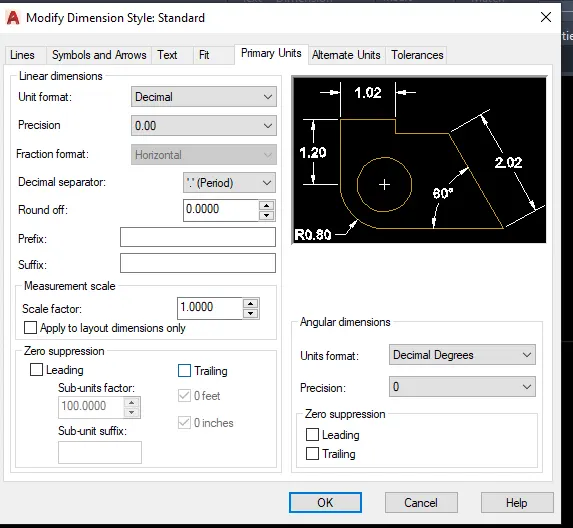
Now, Press on polar tracking and set it on 45,90,135
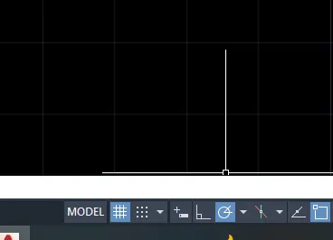
Steps:- PL enter>3 enter
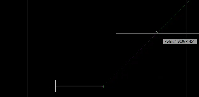
As polar tracking is on we need not manually put the angles as shown.
Just by tracing the cursor at angles of 45,90,135 and putting the length values as 3>2.12>2.83>2 a preliminary drawing will be formed.
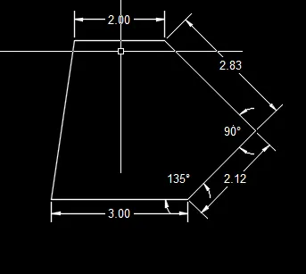
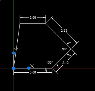
Move the entire drawing to co-ordinate 0,0 as shown.
Select circle with diameter and enter the coordinate (1.5,1) and place the diameter value
as 1.2.Similarly, Select circle with dia or C-Enter place coordinate value as (1.5,2.5)
and diameter value as 0.8.
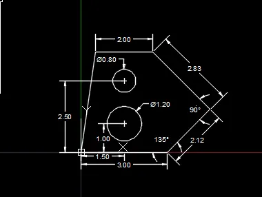
Solution complete.
Solution P-2,
Adopting a template from template diaglog box.
Go to new and select tutorial i-Arch. This is a page with all the settings in imperial(feet and inches)
and dimension setting already loaded. Select D-enter and increase the font and arrow size.
Following the process as mentioned above and activating polar tracking.
Steps 1: Pl-Enter>8'>1'9">track it 135>2'10" ENTER
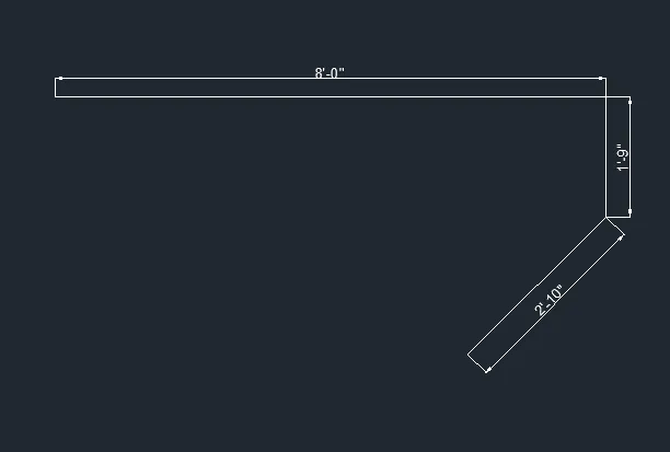
Now, Proceeding to make right side.
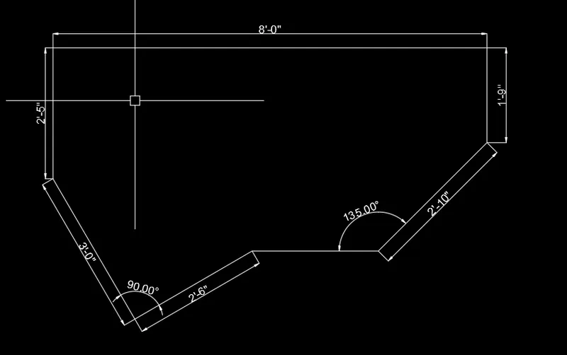
Steps: PL(2'5")>(@3'<300)>Track polar 90>2'6" after polar tracking to 90 degrees.
Result:
Solution P-3,
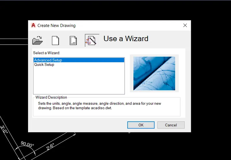
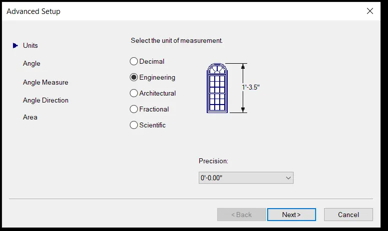
Start by making a new drawing in engineering with a precision of 0'0".
Step1:
Step2:
Step3:
Rec(enter)>choose coordinate point as 0,0.
Enter length=5'0.1"
Enter Breath=3'3"
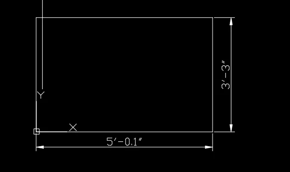
Step 4:
C(enter)>enter coordinates as (1'3",1'6")
Enter the diameter in command line as (1'6")
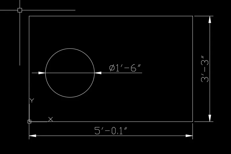
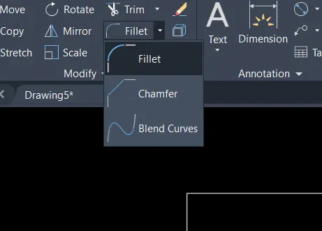
Select Chamfer.
First make dimensions.
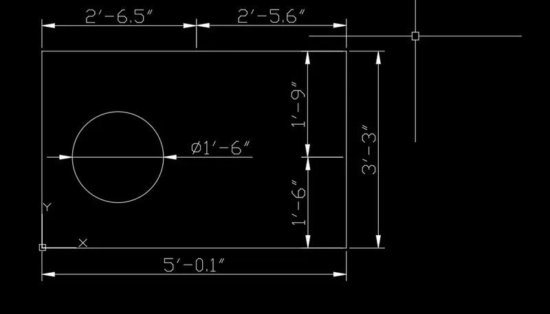
Select Chamfer>select right line>select distance method.
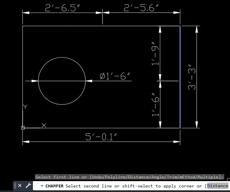
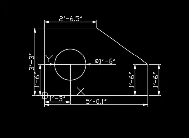
enter first chamfer distance as 1'9" and second chamfer distance as 2'5.6".
Result:
Solution P-4,
This page for initial settings.
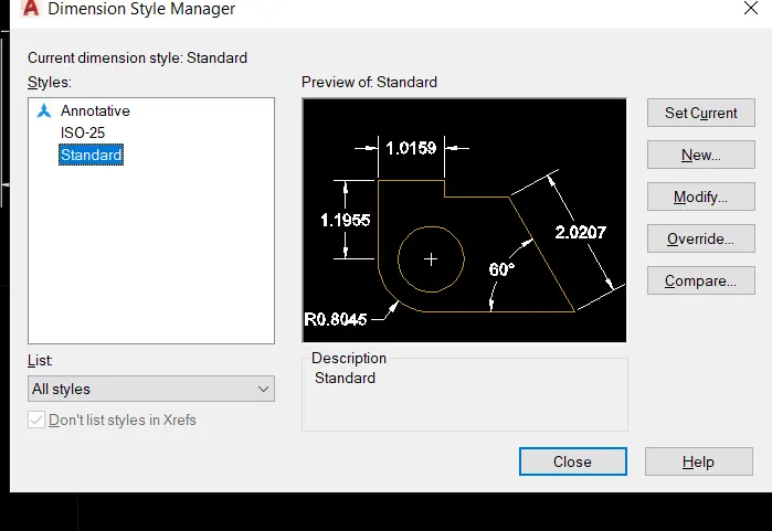
Dimension settings as follows.
Step1:
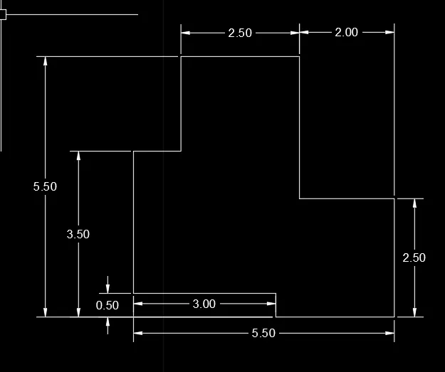
Pl(enter)>3(F8 on and drag right>0.50(drag down)>2.50(drag left)>2.50(drag up)
>2.00(drag left)>3(drag up)>2.50(drag left)>2(drag down)>1(drag left)>close.
Result:
Solution P-5,
On same page as of P-4.
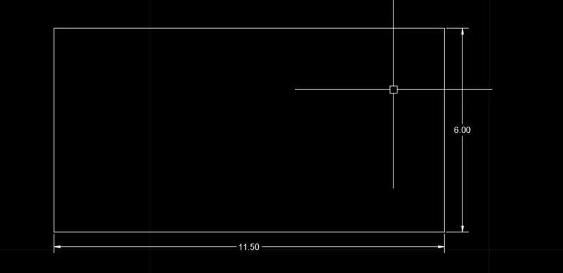
Create a rectangle of 11.50x6 using rec command.
Step 2:
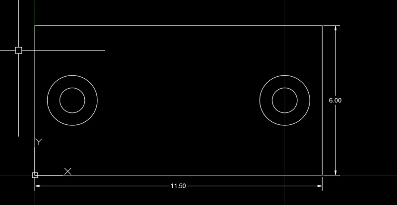
Select "circle with diameter" and then use coordinate system and place the coordinate as (1.5,3) and
create a circle of diameter 1 and 2 respectively. Circles can also be created by snap on.
Copy both circles use Centre point as pick point, f8 on and on the right side give the value of 8.50.
Step 3:
Keeping snap on now at the center of rectangle make a circle of diameter 3.
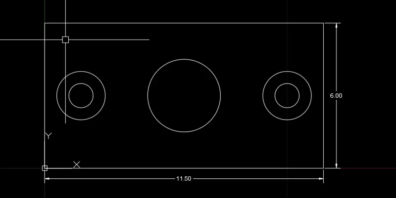
create a line in center and offset it 2.75 left and 2.75 right.
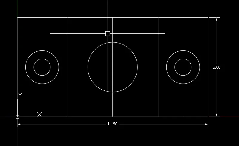
Now, erase the center line.
Result:
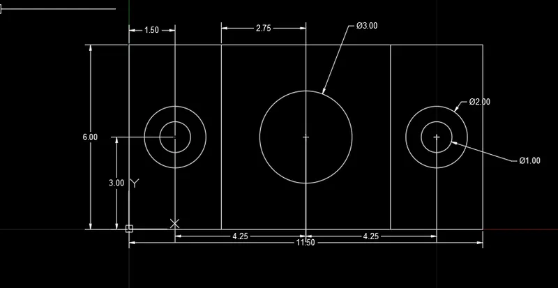
Solution P-6,
Top, front and side view of an object are shown. Analyzing the images, we can find lengths of different sides.
Set the dimension preference to (0.0) using dimension tool or d-enter.
Using Line and Offset command.
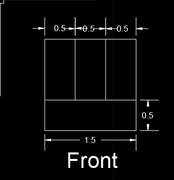
Steps for top view.
A.) Using Rec create a rectangle of 2x1.5.
B.) Explode
C.) OFFSET the length two times by 0.5
D.) Offset (o-enter) the width 0.5.
E.) Trim unnecessary parts.
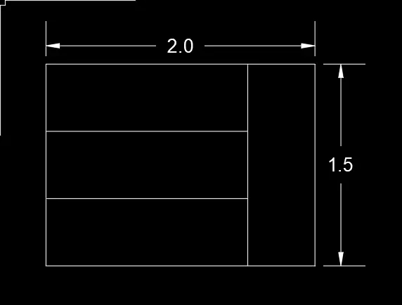
Steps for Side view.
Creating using line command.
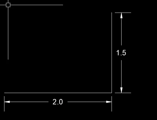
Offset(o-enter) by 0.5 and trim command to trim the parts not necessary.
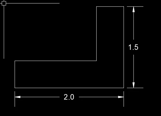
Finishing it off using line command.
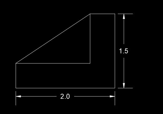
Solution P-7,
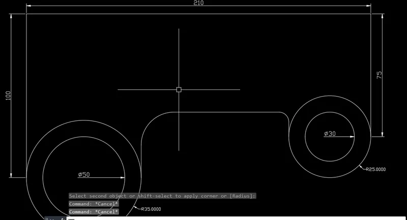
Step 1: PL>100(UP)>210(RIGHT)>75(DOWN)>CLOSE
Step 2: Create 4 circles using the circle-diameter and circle radius both of the given radius as shown.
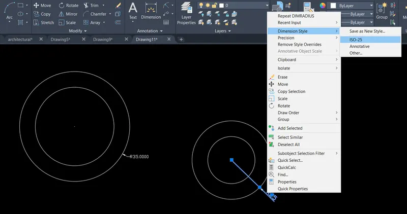
Set dimension style to annotative.
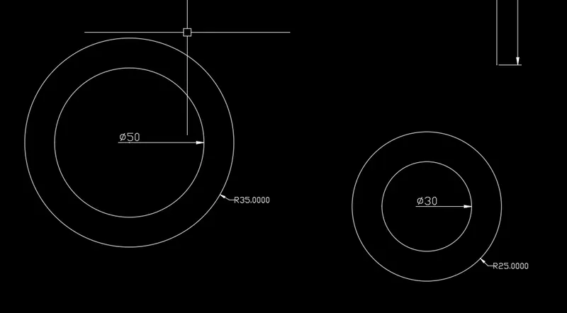
Step 3: Using Snap on> choosing quadrant on>move the respective circles to the endpoint of 100 and 75.
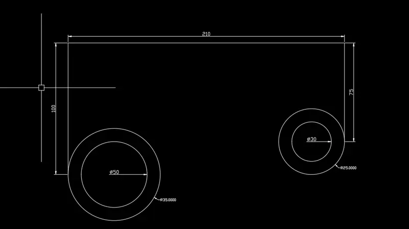
Step 4:
O enter>60(top line)
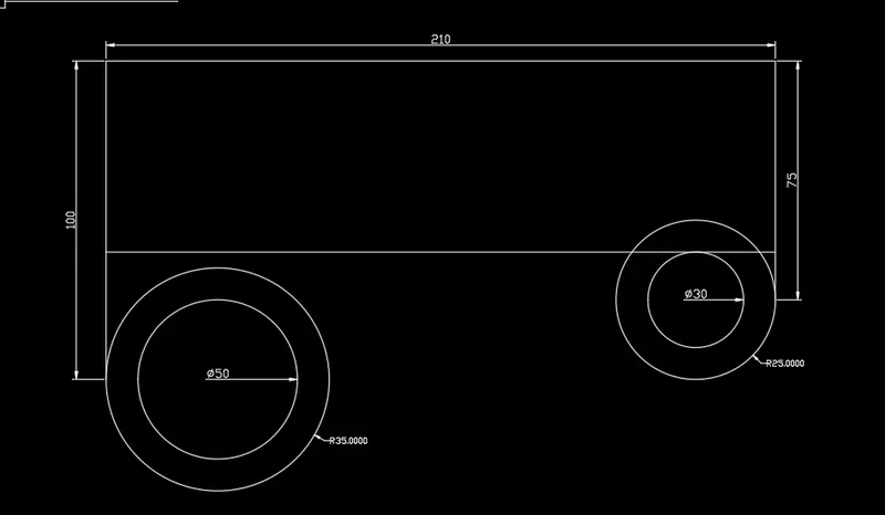
Line command and from quadrant of both circle join it with offset line and trim the unnecessary parts.
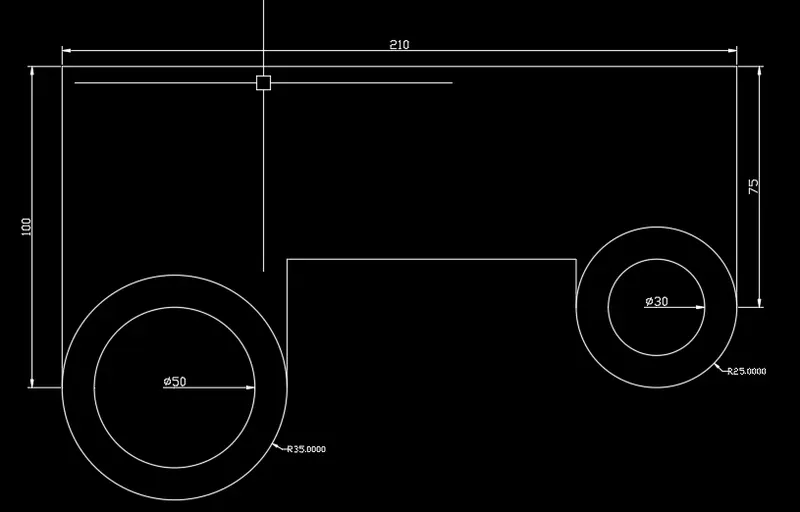
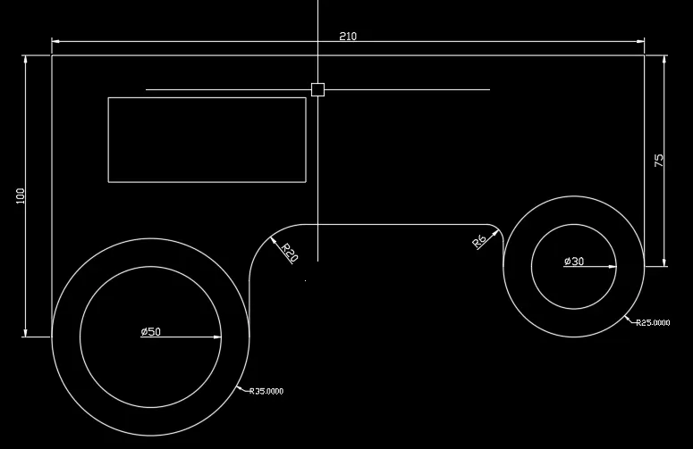
Use fillet command and fillet by choosing radius as 20 and 6.
Rec command >length=70, width=30.
Move the rectangle at (@20, -10)
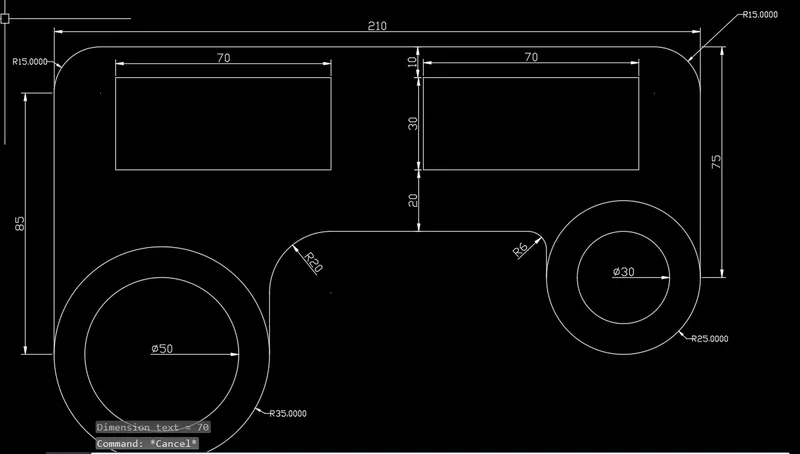
Mirror from middle and fillet using radius of 15.
Result:
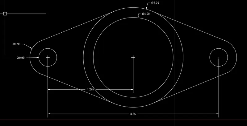
Solution P-8,
c-enter>dia-0.9
c-enter>radius-0.9
center to be same for both.
Copy the circle and using center drag 8.55.
C-enter>dia 5>m2p(between two circle)
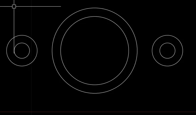
Use line command and join it, keep snap on at all the times.
Result:
Solution P-9,
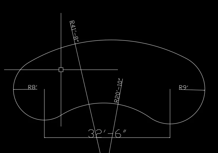
Create two circles one with radius 8' and other with radius 9'. copy the 9' radius circle at a center-to-center distance of 32'6".
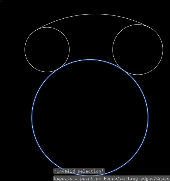
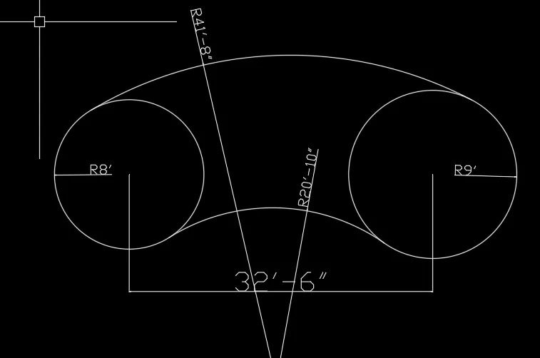
Use trim command to complete.
Solution P-10,
Steps: Since dimensions are not available make a rectangle using Rec command(R-Enter) than Offset it by 0.5
using o-enter and place value.
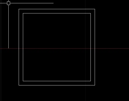
Copy it and paste it at same point and rotate(R-enter) using center point by 45 degrees.
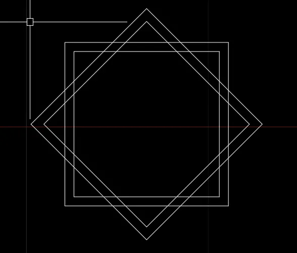
Tr-enter and trim the unnecessary portions.
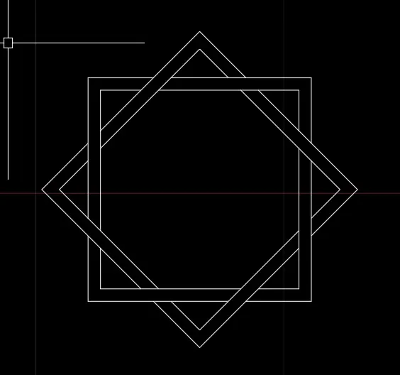
Solution P-11,
l-enter: 1'2" down>4'6"right>4'6"up>3'(right)>9'(up)>10'2">mirror (Keep the source object).
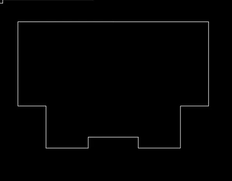
construct a center line and from the mid-point construct a square of 3'x3' using rec command.
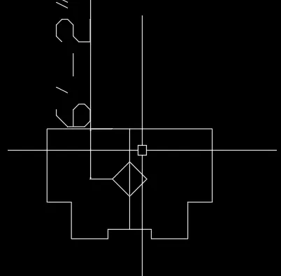
move the square 7" down.
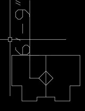
Using m2p command construct a line one of 2'8" and other of 10'2" on each segment taking center line as reference or we can keep the snap on and point construct line.
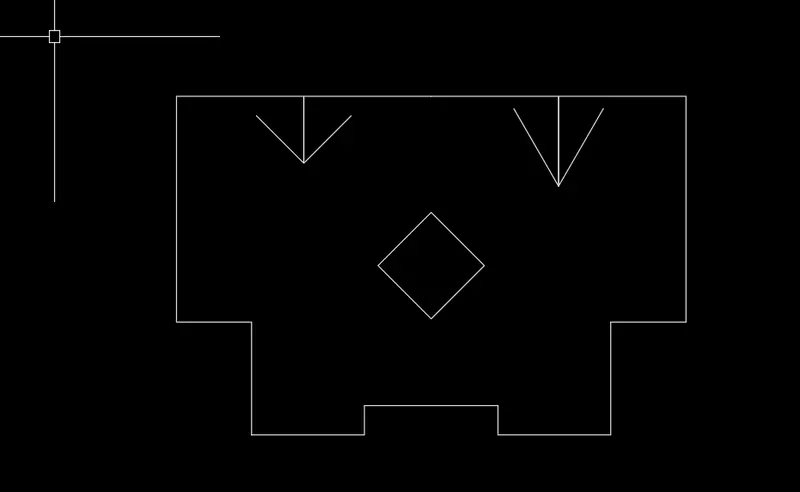
use tr-enter and trimming the unnecessary lines also using extend to join.