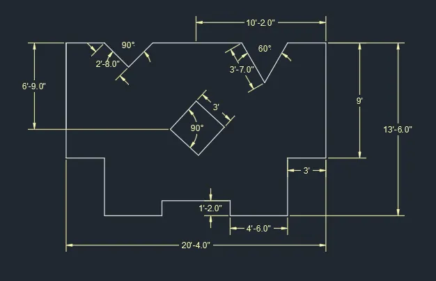
Drafting of various geometries using Chamfer, Fillet tool in AutoCad
Aim – To draw the given geometries using the AutoCAD software.
Procedure:
Figure 1-
- Open AutoCAD software and click on wizard, then the advance settings and set the units as decimal.
- Set the angle in degree with base angle as east and mark the angle direction in the anticlockwise direction
- Type the command units and set to the decimal units.
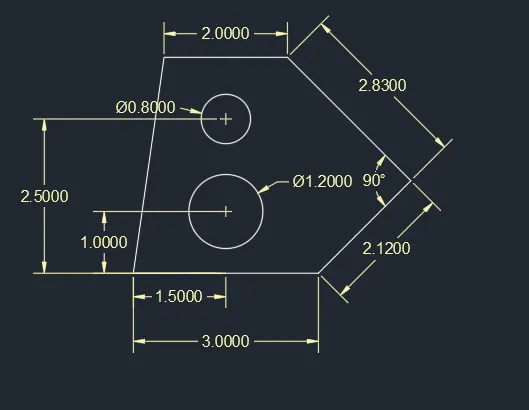
- Type the line command L and specify the first point and now give the length of 3 units in +x axis direction.
- Type the next point @2.12<45
- Type the next point @ 2.83<135
- Move the cursor to the left in –x axis direction and type the next point 2 units.
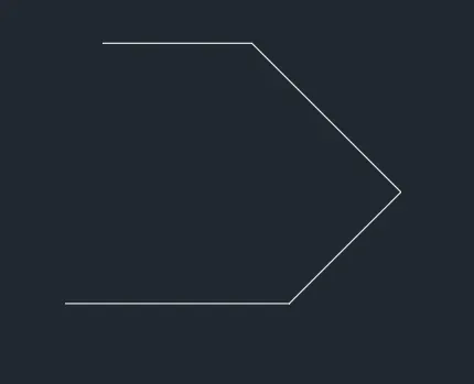
- Now click on the close or the starting point the close irregular polygon.
- Now from the last point give the length of 1.5 unit in +X direction keeping the ortho mode on.
- Now from this point give the length of 1 unit and 2.5 units in +y axis direction.
- Now type the circle command C and make a circle of 1.20 units diameter taking the center as 1unit line point.
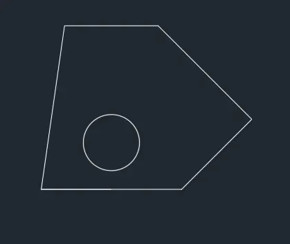
- Now type the circle command C and make a circle of .80 units diameter taking the center as 2.50 units line point.
- Type the trim command and trim these lines after making the circle.
- Do the dimensioning
Result : Geometry is drawn and created as per given.
Aim – To draw the given geometries using the AutoCAD software.
Procedure:
Figure 2-
- Open AutoCAD software and click on wizard, then the advance settings and set the units as Architectural.
- Set the angle in degree with base angle as east and mark the angle direction in the anticlockwise direction
- Type the command units and set to the Architectural units.
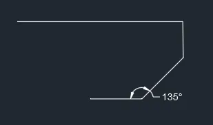
- Keeping the orthomode off make the line of 2’10” in inclined direction
- Now make the line in +y axis direction by giving the length of 1’9”
- Now make the line –x axis direction near the starting point of desired length able to see in the figure
- Now use the move command M and join the last drawn line and the line of 1’9”
- Check the angle and adjust it to 135 degree by using the rotate command
- Now again use the move command M and join this part to 2’10” line
- Now use line command L and make a line of 8’ in –x axis direction from the line 1’9”.
- Now leave this part and make the second part at another space
- Make the line of 2’6” inches in the incline direction.
- Now again make a line of 3’ in + y axis inclined direction
- Now join these two lines using the move command M and check the angle
- If angle is greater and smaller than 90 degree then readjust the 2’6” line by using the rotate command and giving the specified degree of rotation
- Now make the line of 2’5” in +y axis direction from the 3’ line.
- Now select this part and type block command B and make it as a block and name it according to your choice.
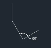
- Now type move command M and select this part and join it to another part which is drawn.
- Now do the dimensioning.
Result: Geometry is drawn and created as per given.
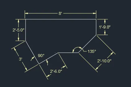
Aim – To draw the given geometries using the AutoCAD software.
Procedure:
Figure 3-
- Open AutoCAD software and click on wizard, then the advance settings and set the units as Engineering.
- Set the angle in degree with base angle as east and mark the angle direction in the anticlockwise direction
- Type the command units and set to the Engineering units.
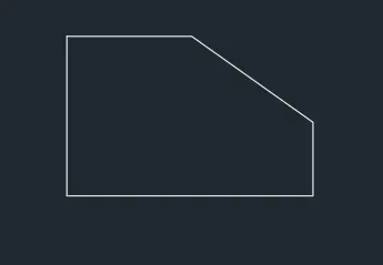
- Type the line command L and give the first point to specify the corner
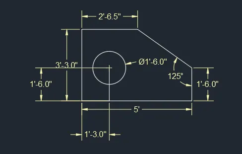
- Now give the length 0f 5’0.1” in +x axis direction.
- From the last point move the cursor in +y axis direction and give the length of 1’6.0”
- Now from the first starting point give the length of 3’3” in +y axis direction
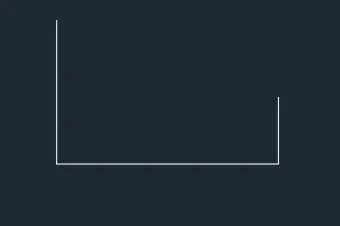
- Now give the length of 2’6.5” in +x axis direction
- Now join the lines to get the close geometry and keep the ortho mode off
- Now from the first starting point give the length of 1’3” in +x axis direction
- Now give the length of 1’6” in +y axis direction
- Now type the circle command C and make a circle of diameter 1’6” by clicking on diameter in the command box
Result: The geometry is drawn and created as per given
Aim – To draw the given geometries using the AutoCAD software.
Procedure:
Figure 4-
- Open AutoCAD software and click on wizard, then the advance settings and set the units as Decimal.
- Set the angle in degree with base angle as east and mark the angle direction in the anticlockwise direction
- Type the command units and set to the Decimal units.
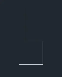
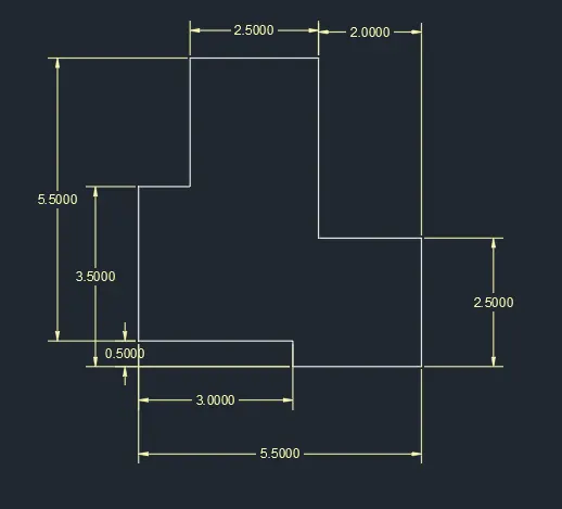
- Type the line command L and specify the first corner point.
- Now move the cursor in +x axis direction and give the length of 2.50 units in command box.
- Now move the cursor in +y axis direction and give the length of 2.50 units in command box.
- Now move the cursor in –x axis direction and give the length of 2.00 units in command box.
- Now move the cursor in +y axis direction and give the length of 3.50 units in command box.
- Now move the cursor in –x axis direction and give the length of 2.50 units in command box.
- Now move the cursor in –y axis direction and give the length of 2.50 units in command box.
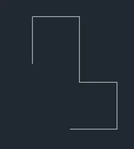
- Now move the cursor in –x axis direction and give the length of 1.00 units in command box.
- Now move the cursor in –y axis direction and give the length of 3.00 units in command box.
- Now move the cursor in +axis direction and give the length of 3.00 units in command box.
- Now move the cursor in –y axis direction and give the length of 0.50 units in command box or click the close command.
Result: The geometry is drawn and created as per given.
Aim – To draw the given geometries using the AutoCAD software.
Procedure:
Figure 5-
- Open AutoCAD software and click on wizard, then the advance settings and set the units as Decimal.
- Set the angle in degree with base angle as east and mark the angle direction in the anticlockwise direction
- Type the command units and set to the Decimal units.
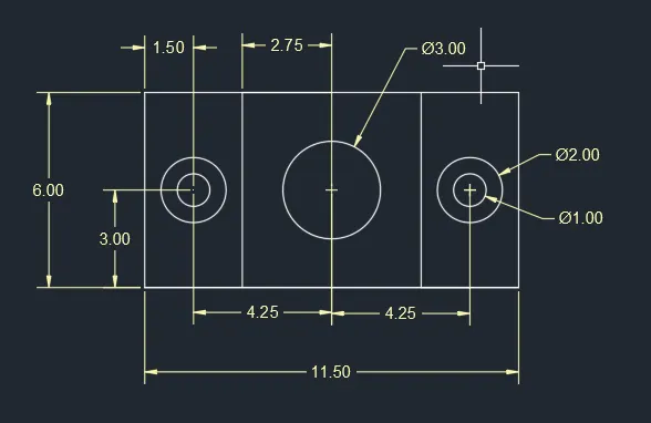
- Type the rectangle command REC and specify the first corner point.
- Click on the dimension in the command box and give the length= 11.50 and width = 6.0 units
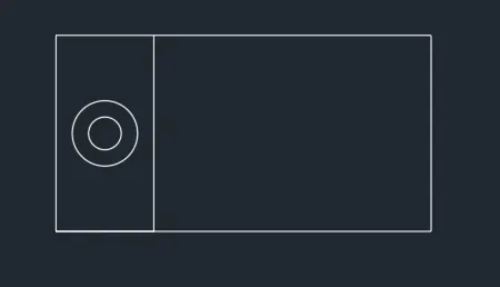
- Type the line command L and now from the starting corner point give the length of 1.50 units
- Now in +y direction give the length of 3 units
- Now type circle command C and click the centre point which is the last point
- Make the circle of diameter 1 unit
- Now again click on the same centre point and make a circle of 2 units.
- Now trim the 3 unit line which is in the +y axis direction
- Now from the 1.50 unit line which is in +x axis direction, again make the length of 1.50 unit in same direction
- Now give perpendicular of 6 units
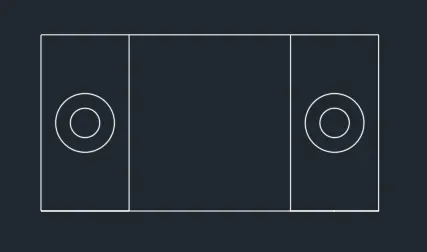
- Now repeat the same process from the opposite side to get the same mirror type view of the geometry.
- Now from the last point give the length of 2.75 units in –x axis direction
- Now give the length of 3 units in –y axis direction
- Now type circle command C specify the last point as centre point
- Now from this point make a circle of diameter 3 units.
- Now trim the 3 unit line in –y axis direction.
Result: The geometry is drawn and created as per given.
Aim – To draw the given geometries using the AutoCAD software.
Procedure:
Figure 6-
- Open AutoCAD software and click on wizard, then the advance settings and set the units as Decimal.
- Set the angle in degree with base angle as east and mark the angle direction in the anticlockwise direction
- Type the command units and set to the Decimal units.
- Type the Line command L and specify the corner point
- Now make the line of 1.5 units in +y axis direction using the line command L
- Now make the line of 0.5 units in -x axis direction using the line command L
- Now make the line of 1 units in -y axis direction using the line command L
- Now make the line of 1.5 units in -x axis direction using the line command L
- Now make the line of 0.5 units in -y axis direction using the line command L
- Now make the line of 2.0 units in +x axis direction using the line command L
- Join the diagonal points making a line as shown in the figure keeping the ortho mode off.

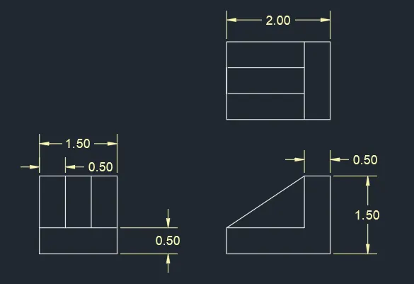
- Now from the upper point of 1.5 units line in +y axis direction, keeping the extension mode on, make the line of 1.5 unit in +y axis direction at some distance from lower geometry
- Now make the line of 0.5 units in -x axis direction using the line command L
- Now make the line of 1.5 units in -y axis direction using the line command L
- Now make the line of 0.5 units in +x axis direction using the line command L
- Now make a line of 1.5 unit from the lower left corner of rectangle in –x axis direction.
- Now make the line of 0.5 units in +y axis direction using the line command L
- Now make the line of 1.5 units in +x axis direction using the line command L
- Now type the copy command and copy this rectangle and make other two rectangles.
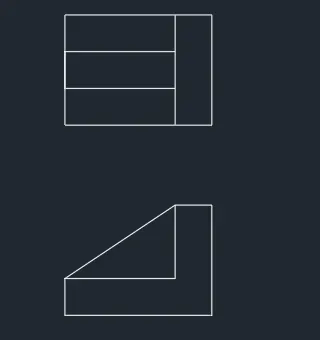
- Now from the left lower point of 1st geometry, keeping extension line mode on and at some distance in the same line draw a line of 1.5 units in –x direction
- Now make the line of 0.5 units in +y axis direction using the line command L
- Now make the line of 1.5 units in -x axis direction using the line command L
- Now make the line of 0.5 units in -y axis direction using the line command L
- Repeat the previous process for making rectangles with the help of copy command.
- Geometry is drawn and dimensioning is done.
Result: The geometry is drawn and created as per given.
Aim – To draw the given geometries using the AutoCAD software.
Procedure:
Figure 8-
- Open AutoCAD software and click on wizard, then the advance settings and set the units as Decimal.
- Set the angle in degree with base angle as east and mark the angle direction in the anticlockwise direction
- Type the command units and set to the Decimal units.
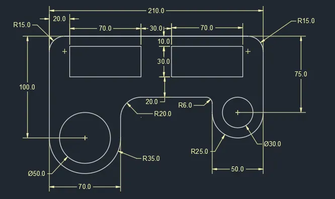
- Type the Line command L and specify the corner point
- Now make the line of 100 units in +y axis direction using the line command L
- Now make the line of 210 units in +x axis direction using the line command L
- Now make the line of 75 units in -y axis direction using the line command L
- Now use the “start end radius” from the arc option and select the first point which is the last point just made and second point to 50 unit in – x direction keeping ortho mode on
- Type the Radius as 25 unit and an arc will be drawn.
- Now make the line of 15 units in +y axis direction using the line command L
- Now make the line of 90 units in -x axis direction using the line command L
- Now make the line of 40 units in -y axis direction using the line command L
- Now again use the arc option and select “start end radius” and select the two points, then give the radius of 35 units
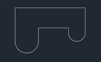
- Now from the upper left corner point make a line of 20 unit in +x axis direction and 10 units in –y direction to get the corner point of rectangle
- Now type the rectangle command REC, click on the corner point and give the dimensions, length as 70 units and width as 30 units.
- Do the same for other side to get the same rectangle.
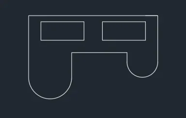
- Now use the FILLET command to give the radius to the upper left corner point of the main geometry.
- Type the fillet command and enter the radius as 15 units.
- Now select the two lines meeting at that corner and click it, the line will become curve type
- Do the same for all other corners by giving the specified radius
- Now from the centre of the arc make a circle of 50 unit diameter by typing circle command C and entering the diameter.
- Now do the same for the other side by giving the diameter of circle as 30 unit.
Result: The geometery is drawn and created as per given.
Aim – To draw the given geometries using the AutoCAD software.
Procedure:
Figure 8-
- Open AutoCAD software and click on wizard, then the advance settings and set the units as Decimal.
- Set the angle in degree with base angle as east and mark the angle direction in the anticlockwise direction
- Type the command units and set to the Decimal units.
- Type the Line command L and specify the corner point
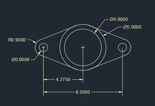
- Now make the line of 8.55 units in +x axis direction using the line command L
- Now click on left corner and type the circle command C and give the diameter of 0.90 units.
- Now click on the mirror option selecting first point as circle centre and second point as mid-point of line. Click it and mirror image will be drawn on other side
- Now again from the centre of the first circle draw one more circle of 0.90 radius.
- Now again use mirror option and repeat the process as earlier

- Now click on centre of line and type the circle command c and make a circle of 4 and 5 units diameter
- Now trim the middle line using the trim command
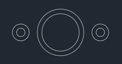
- Type line command L and join the line from upper part circumference and lower part circumference of 5 unit diameter circle to the another two circles of 0.90 diameter.
- Now use the trim command to get the same geometry as given.
Result: The geometry is drawn and created as per given.
Aim – To draw the given geometries using the AutoCAD software.
Procedure:
Figure 9-
- Open AutoCAD software and click on wizard, then the advance settings and set the units as Engineering
- Set the angle in degree with base angle as east and mark the angle direction in the anticlockwise direction
- Type the command units and set to the Engineering units.
- Type the Line command L and specify the corner point
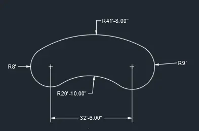
- Now make the line of 32’6” units in +x axis direction using the line command L
- Now from the left corner make a circle of 8’radius by typing circle command C and giving the radius.
- Now from the right corner make a circle of 9’ unit radius by typing circle command C and giving the radius.
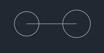
- Now from the circle option use “tan tan radius” option to get same geometry
- After selecting the option, select the two points. The first point is lower circumference point of 8’ radius and second point is lower circumference point of 9’ radius.
- Give the radius as 20’10”.
- Now again use the “tan tan radius” option and click the two points. First point is left circumference point of 8’ radius circle and second point is right circumference point of 9’ radius circle.
- Now give the radius as 41’8”
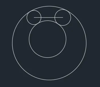
- Now trim the lines using the trim command.
Result: The geometry is drawn and created as per given
Aim – To draw the given geometries using the AutoCAD software.
Procedure:
Figure 10-
- Open AutoCAD software and click on wizard, then the advance settings and set the units as Decimal
- Set the angle in degree with base angle as east and mark the angle direction in the anticlockwise direction
- Type the command units and set to the Decimal units.
- Type the rectangle command and give the diameter of length of 8 units and width of 8 units
- Use the offset command and give a length of 0.5 unit
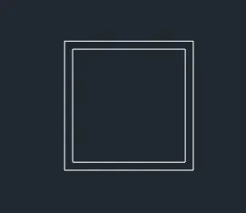
- Now again make a square of 8 units using the REC command at another space and use offset command same as earlier of 0.5 units.
- Rotate the square to specified angle and match the rotated corner of square to the centre line of normal square.

- Type the move command and move the rotated square to the desired distance to get the same exact geometry.
Result: The geometry is drawn and created as per given

Aim – To draw the given geometries using the AutoCAD software.
Procedure:
Figure 11-
- Open AutoCAD software and click on wizard, then the advance settings and set the units as Engineering
- Set the angle in degree with base angle as east and mark the angle direction in the anticlockwise direction
- Type the command units and set to the Engineering units.
- Now make the line of 9’ in +y axis direction using the line command L
- Now make the line of 3’ in +x axis direction using the line command L
- Type a line command L and give point @2’8”<-45
- Type a line command L and give point @2’8”<45
- Now exactly do same for the opposite side
- Now from the start point make a length of 20’4” in +x axis direction.
- Now make the line of 9’ in +y axis direction using the line command L
- Now make the line of 3’ in -x axis direction using the line command L
- Type a line command L and give point @3’7”<-120
- Type a line command L and give point @3’7”<120
- Now join the points to get an upper middle horizontal line.
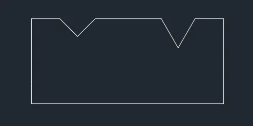
- Now erase the 20’4”line
- Now make the line of 3’ in -x axis direction using the line command L
- Now make the line of 4’6” in -y axis direction using the line command L
- Now make the line of 4’6” in -x axis direction using the line command L
- Now make the line of 1’2” in +y axis direction using the line command L
- Repeat the exact process from the other side as the dimensions are same.
- Now join the two point to get lower middle horizontal line
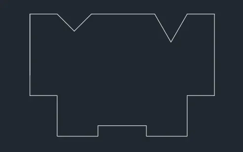
- Now from the upper left corner of geometry, making a point 6’9” down in –y direction, make a horizontal line touching other end
- Make a square of 3’ by typing REC in command box and clicking on the dimensions give the length as 3’ and width as 3’
- Rotate the square to the specified angle near to 45 degree
- Match the rotated corner of square to last horizontal line made
- Bring it to the centre and match the centre point of the line and centre point of the square.
Result: The geometry is drawn and created as per given.