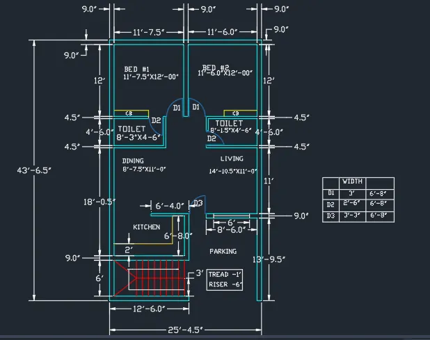
Creating a Residence Layout, Seating plan, Toilet and Utility room plan using AutoCad
1. RESIDENTIAL PLAN
Aim – TO sketch a residence layout using AutoCAD software
Procedure:
- First create a new autocad file with imperial units
- Type the command units and set it to architectural units
- Set the limits by using LIMITS command and specify the left corner point and then right corner point.
- Draw the construction lines by command “XL-V” for vertical and “XL-H” for horizontal.
- Now using trim command trim the left side and the top side of construction line.
- Drawing bedroom 1
- Type the offset command and give an offset of 9” to both the construction lines for getting the boundary thickness.
- Then take an offset of 11’7.5” in horizontal direction and 12’ offset in vertical direction
- Again give an offset of 4.5” to both the sides so that the thickness of the wall is created
- Now trim the extra lines using the trim command
- Now drawing bedroom 2
- Give an offset of 11’6” in horizontal direction from the bedroom 1 wall
- Again give an offset of 9” in same direction for the boundary thickness
- Now extend the 12’ line from bedroom 1 till this boundary line using the extend command
- Now trim the desired line using trim command
- Now drawing Toilet 1
- Give an offset of 4’6” in downward direction from the from the wall of bedroom 1
- Again an offset of 4.5” for the thickness of wall
- Now from the left wall boundary of 9” give the offset 8’3” inches in +x direction.
- Again an offset of 4.5” for thickness in +x direction
- Trim the unwanted lines using the TRIM command
- Now drawing Toilet 2
- From the right boundary and corner of bedroom 2 extend the line to 4’6” in –y direction and again extending 4.5” for thickness
- Now give the offset of 9” for thickness
- Now from 4’6” line give the offset 8’1.5” in –x direction.
- Trim the unwanted lines using the trim command
- Now drawing living room and dining hall
- From the right boundary and corner of toilet 2 ,extend a line to 11’ in –y direction and again extend to 9” in same direction for thickness
- Now give the offset of 9” in –x direction for thickness of boundary
- Now make a line of 8’6” in –x direction from the 11’ line using line command
- Now make a line 4.5” in –y direction
- Join it to thickness point
- Now for dining give the offset 18’0.5” from the toilet 1 and again give the offset of 9” in –y direction
- Extend the line if desired to get the corner points
- Now from 18’0.5”linr give the offset of 12’6” in +x direction.
- Again give the offset of 9” in the same direction for the thickness
- Now extend the living room boundary to trim the extra vertical line
- Now again erase that extended line
- Now from outer vertical boundary line of kitchen in right side make a line 6’4” in –x direction
- Now make a line of 4.5” in –y direction for thickness and join the vertical line in the right.
- Trim the unwanted lines
- For Making kitchen
- Now from the inner horizontal wall make a offset of 2’
- Same for the vertical inner line make an offset of 2’
- Trim the unwanted lines.
- Making the parking space.
- Now from the outer horizontal boundary of kitchen give an offset of 6’
- Again give an offset of 9” for thickness
- Now from the corner of living room join the lines in the downward vertical direction to get the parking space
- Trim the unwanted lines
- Making the stairs
- Now from the outer vertical wall of kitchen draw a perpendicular to get the 12’6” distance.
- Trim the unwanted lines.
- Now from the left corner at 11’6” make a vertical line of 3’ and a horizontal line (railing) till vertical boundary.
- Now give required multiple offset of 1’ by counting stairs.
- From these stairs make a dotted line using layer properties and join perpendicular to other line making upward direction stairs
- Make a line with arrow to tell the direction of stairs using the leader (Annotation)
- Specify the tread and riser in rectangle.
- Making doors
- Create the opening for respective doors using the width given in table
- Leave the 2” from both the corners of doors and give the required height as given in table
- Now use the “start, end, direction” option from the arc in the ribbon to make the door. Use this for all doors.
- Now select the doors and click on by layer (properties) to give the required colour
- Making Cupboard
- Now draw the cupboard by making a rectangle specifying the base point and giving dimensions as 5’1”x2’
- Copy and place it to the other bedroom
- Use layers options
- Create layers for every part like wall, windows cupboard ,stairs etc. so that it can be distinguished by giving different colours
- Select and place as individual layer.
- Do the dimensioning of the whole plan
Result: Resisential paln has been drawn in Architectural units and as per given.
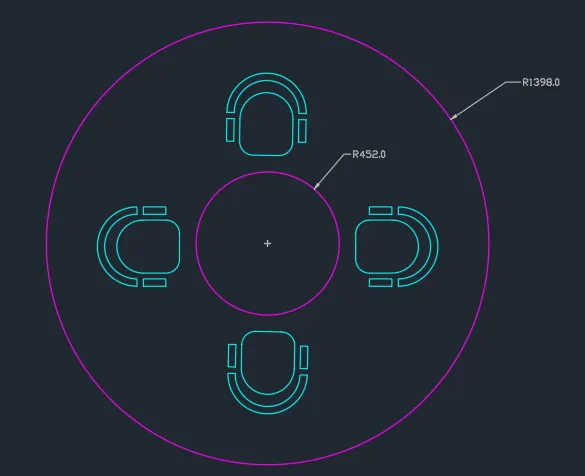
2. SEATING PLAN FOR AN OUTDOOR CANOPY
Aim – To sketch a plan for an outdoor canopy by assuming dimensions as required using AutoCAD software
Procedure:
- First create a new Autocad file with metric units
- Type the command units and set it to decimal units
- Set the limits by using LIMITS command and specify the ends points.
- Type the circle command and make a circle by giving the radius of 452 mm in command box.
- Now from the same centre point make another circle by giving the radius of 1398 mm in the command box.
- Now making the chairs.
- Extend a line from centre of the circle in the right direction for making the chair to set in proper alignment so that when we move it in the circle, its middle should come in centre.
- Now make a U using line command and of desired length as seen in geometry and the open face of the U should be in right.
- Now using the “start end direction” from the arc option make a arc from corners of U.
- Now using the fillet command turn the corners by clicking on both the joining lines
- From the upper horizontal length just before arc give the offset to small distance in +y direction so that rectangle should be made.
- Now use the mirror command to obtain the same rectangle in lower side.
- Now from right vertical line of small rectangle give the offset in +x direction to small distance.
- Again use the mirror command to get same vertical line at lower side.
- Now use the “start end direction” from the arc option for making inner and outer arc taking the corners of vertical lines.
- Chair has been made.
- Use the move command to and select the chair. Move it to the exact on the centre line which we had drawn earlier.
- Now use the MIRROR command and place the rest of the chairs in the exact position as shown in geometry.
- Geometry has been created.
Result: Outdoor canopy seating plan has been created as per given and assuming the dimensions required.
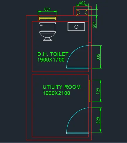
3. PART PLAN OF A RESIDENTIAL BUILDING
Aim – To sketch a part plan for the toilet and utility room and assuming the required dimensions, using AutoCAD software
Procedure:
- First create a new Autocad file with metric units
- Type the command units and set it to decimal units
- Set the limits by using LIMITS command and specify the left corner point and then right corner point.
- Draw the construction lines by command “XL-V” for vertical and “XL-H” for horizontal.
- Now using trim command trim the left side and the top side of construction line.
- Drawing the utility room first
- Give the offset of 300 mm by from the vertical X line in +x axis direction
- Now again give the offset of 150 mm from the horizontal X line in +y direction.
- Now give the offset of 1900 mm from the 300 mm line in +x direction
- Give the offset of 150 mm for thickness of wall in +x direction.
- Now give the offset of 2100 mm from the 150mm line in +y axis direction.
- Trim the unwanted line using trim command
- Drawing D.H Toilet
- Now from the upward horizontal boundary of utility room give an offset of 150 mm in +y direction
- Now from the vertical X line again give the offset of 300mm.
- Now from this line again give the offset of 1900 mm in +x direction and 150 mm offset for thickness in same direction
- Now from the lower horizontal boundary of toilet give the offset of 1700 mm in +y direction and an offset of300 mm for thickness.
- Trim the unwanted lines using the trim command
- Making exhaust
- From the right upper corner of plan make a line of 201 in +y direction
- Make a 150 mm line in again from the last point in +y direction.
- Again make a line of 402 mm in –x direction.
- Now from last vertical line make the required offsets 0f 100mm, then 402 mm and then again 100mm in –x direction.
- Make the one inner diagonal line by L Command then use mirror command to obtain rest lines.
- Making V2 ventilator
- From the upper left corner of toilet, from inner left vertical boundary give the offset of 100 mm in +x direction
- Again give the offset of 631mm in same direction.
- Now make the required lines by using line command
- Do the same for utility room window
- Give the 150 mm offset from the upward corner to corner of window.
- Now give the offset of 728 mm in same direction
- Now again give the offset of 300mm to get the corner of door.
- Now making door of utility room
- Give the offset of 828 mm from the last point
- Now from this give the desired height of door as seen in geometry.
- Use the “start end direction” from the arc ribbon option and make an arc for a door as specified
- D.H toilet door
- Give the offset from the lower boundary of toilet, from corner of 100mm and then give the offset of 832 mm in the same direction.
- Again give the offset of 100 mm in same direction to get the corner thickness of door.
- Repeat the previous process for getting the arc and making the door.
- Go to tool options and from tool palettes select the fluorescent and toilet and use them in the geometry.
- Decrease the size if large using the scale options.
- Colour the required wall, window, door etc. using layer options and giving desired colour.
- Geometry has been created in the form of part plan
Result: Residential part plan has been drawn in metric units of toilet and utility room.